Материал: m083300e
Fieldbus coupler / controller |
• 27 |
Fieldbus coupler 750-333 |
|
|
|
3.1.3Operating system
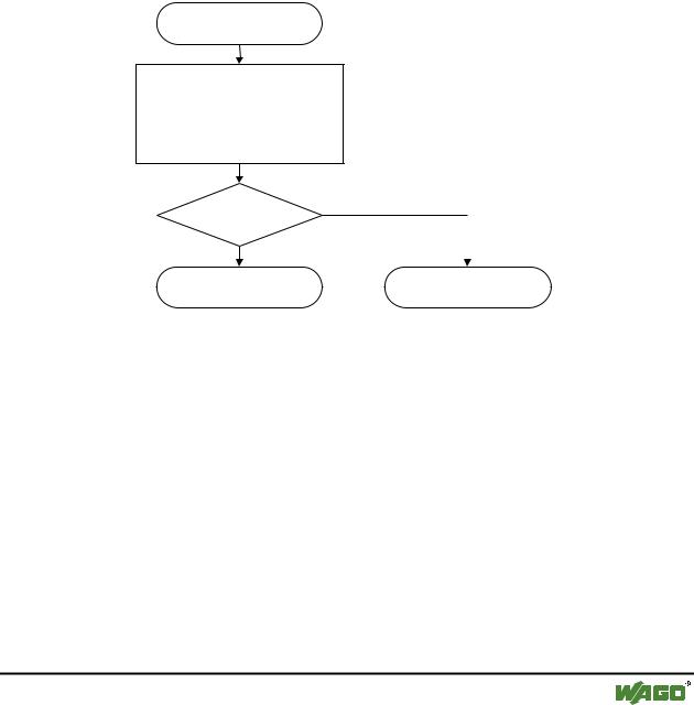
Following the configuration of the master activation and the electrical installation if the fieldbus station can start up the system.
After switching on the supply voltage the coupler performs a self test of all functions of its devices, the I/O module and the fieldbus interface. Following this the I/O modules and the present configuration is determined, whereby an external not visible list is generated. This list includes an input and an output area on which is represented the fieldbus RAM of the protocol chip.
In the event of a fault the coupler changes to the "Stop" condition. The "I/O" LED flashes red. After a fault free start up the coupler changes to the "Fieldbus start" status and the "I/O" LED lights up green.
Versorgungsspannung
einschalten
Koppler-Selbsttest,
Ermittlung Busklemmen
und Konfiguration,
Erstellung interner Liste
“I/O”-LED blinkt rot
Ja |
|
|
Fehler |
|
|
|
|
|
Nein |
|
|
|
|
|
Feldbusstart |
Stop |
|
“I/O”-LED leuchtet grün |
“I/O”-LED blinkt rot |
|
Fig. 3-7: Operating system 750-333 |
|
g012113d |
WAGO-I/O-SYSTEM 750 |
D R A F T |
PROFIBUS |
2001-02-27 |
28 • Fieldbus coupler / controller
Fieldbus coupler 750-333
3.1.4Process image
3.1.4.1Local process image
After switching on, the coupler recognises all I/O modules plugged into the node which supply or wait for data (data width/bit width > 0). In nodes analog and digital I/O modules can be mixed.
Note
For the number of input and output bits or bytes of the individually activated on I/O modules please refer to the corresponding I/O module description.
The coupler produces an internal process image from the data width and the type of type of I/O module as well as the position of the I/O modules in the node. It is divided into an input and an output data area.
The data of the digital I/O modules is bit orientated, i.e. the data exchange is made bit for bit. The analog I/O modules are representative for all byte orientated I/O modules, i.e. those where the data exchange is made byte for byte.
These I/O modules include for example the counter modules, I/O modules for angle and path measurement as well as the communication modules.
The data of the I/O modules is separated for the local input and output process image in the sequence of their position after the coupler in the individual process image.
Note
A process image restructuring may result if a node is changed or extended. In this case the process data addresses also change in comparison with earlier ones.
D R A F T |
WAGO-I/O-SYSTEM 750 |
2001-02-27 |
PROFIBUS |
Fieldbus coupler / controller |
• 29 |
Fieldbus coupler 750-333 |
|
|
|
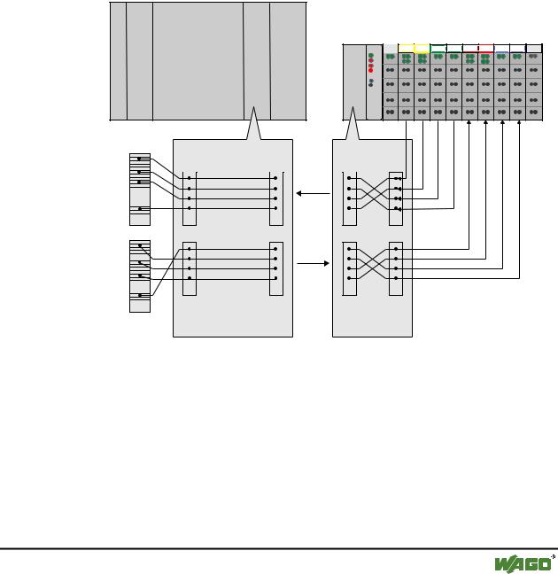
3.1.4.2Allocation of the input and output data
The process data is exchanged via the PROFIBUS with the higher ranking controls (master). A maximum of 128 bytes of data is transmitted from the master to the coupler or from the node to the output data. The coupler responds by returning a maximum of 128 bytes input data to the master.
Modules are configured when projecting the node which can be taken over from a hardware catalogue of the configuration programs. The information covering the possible modules is contained in the GSD files.
The coupler generates an internal mapping in accordance with the installed and configured settings of the node, in which the allocation of the input and output data is determined in the local process image with the position in the PROFIBUS DP Telegram.
Master, z. B. SPS
CPU
Anschaltung |
750- |
1 |
2 |
3 |
4 |
5 |
6 |
7 |
8 |
9 |
|
||||||||||
|
|
DI |
DI |
AI |
AI |
DO DO |
AO AO |
|
||
|
|
402 |
402 |
452 |
452 |
504 |
504 |
550 |
550 |
600 |
Master- |
|
|
|
|
Adressen |
|
|
|
|
I |
|
Zuordnungsliste |
Zuordnungsliste |
|
|
|
|||
|
I |
I |
I |
I |
|
|
|
PROFIBUS |
|
O |
O |
O |
O |
O |
|
|
|
PROFIBUS |
|
bitund byteweise byteweise Zuordnung, Zuordnung, Erstellung auf dem PC
Erstellung automatisch durch den Koppler
Fig. 3-8: Allocation of the input and output data |
g012117d |
WAGO-I/O-SYSTEM 750 |
D R A F T |
PROFIBUS |
2001-02-27 |

30 • Fieldbus coupler / controller
Fieldbus coupler 750-333
3.1.5Configuration
The configuration of the node is performed in accordance with the physical requirements of the fieldbus coupler and I/O modules.
The fieldbus coupler or the process data channel is to be configured on the first slot.
The other slots are configured in accordance with the physical requirements of the I/O modules. Here only I/O modules with process data are relevant. The supply modules without diagnosis, bus internal system supply module and the termination module are to be ignored for the configuration because they do not provide any process data.
One or tow modules are entered in the hardware catalogue for each I/O module. The module appear as 750-xyz ..., for example 750-400 2 DI/24 V DC/3.0
ms.
For all binary modules an addition is made to the entry *750-xyz .... When using these denominations the coupler adds the binary information to the current module in a byte which was previously opened with 750-xyz .... The use of a „*“ module is only permitted when the number of channels is less than or equal to the remaining bits in the previously opened byte. The binary I/O modules combined in a byte can be arranged at separate locations, i.e. binary I/O modules with a different signal type or also byte orientated I/O modules can be connected between.
In order to be able to individually arrange the scope of connected periphery units independent of the control program, it is possible to parameterise I/O modules in the configuration table as „not connected“. In this manner process data still present is filtered for the individual module and not transferred on the PROFIBUS DP to and read by the periphery units.
D R A F T |
WAGO-I/O-SYSTEM 750 |
2001-02-27 |
PROFIBUS |
Fieldbus coupler / controller |
• 31 |
Fieldbus coupler 750-333 |
|
|
|
3.1.5.1GSD files
Under PROFIBUS DP the features of the modules are defined by the manufacturers in the form of a GSD file (unit basic data).
Structure, content and coding of this unit main data are standardised and made available to the user allowing to project optional DP slaves using the project units of various manufacturers.
Further information
i The PNO provides information about the GSD files of all listed manufacturers.
GSD and symbol files for the configuration of the I/O modules are available under the order number 750-910 on disks or from the WAGO INTERNET page.
http://www.wago.com
GSD file for I/O-Module 750-333 |
WAGOB754.GSD |
|
|
The GSD file is read by the configuration software and the corresponding settings transmitted. For the necessary inputs and handling steps please refer to the software user manuals.
WAGO-I/O-SYSTEM 750 |
D R A F T |
PROFIBUS |
2001-02-27 |