Материал: m083300e
32 • Fieldbus coupler / controller
Fieldbus coupler 750-333
3.1.5.2Identification bytes
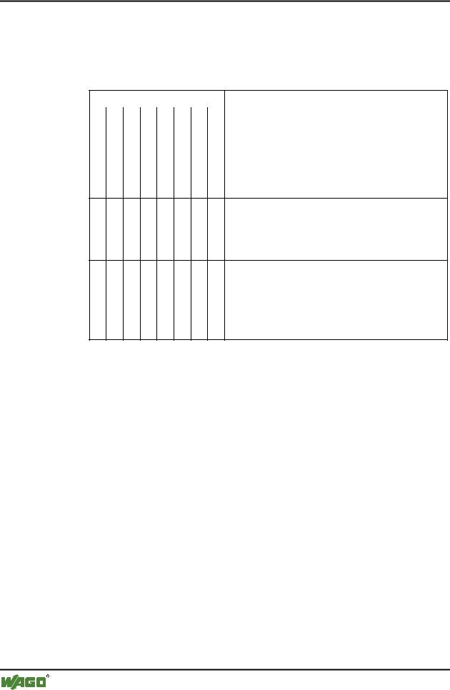
The identification bytes contain information about the design and structure of the unit inputs and outputs. For projecting each I/O module, or each channel is allocated an identification (module).
Bit |
|
|
|
|
|
|
|
Meaning |
7 |
6 |
5 |
4 |
3 |
2 |
1 |
0 |
|
|
|
|
|
|
|
|
|
Data length |
|
|
|
|
0 |
0 |
0 |
0 |
1 byte or word |
|
|
|
|
0 |
0 |
0 |
1 |
2 bytes or words |
|
|
|
|
0 |
0 |
1 |
0 |
3 bytes or words |
|
|
|
|
... ... ... ... ... |
||||
|
|
|
|
1 |
1 |
1 |
1 |
16 bytes or words |
|
|
Input and output |
0 |
0 |
spec. identification formats |
0 |
1 |
Input |
1 |
0 |
Output |
1 |
1 |
Input and output |
|
Format |
|
0 |
0 |
= Byte structure |
1 |
1 |
= Word structure |
|
|
|
|
Consistence over |
|
0 |
Byte or word |
|
1 |
Total length |
|
This information is saved in the GSD file. During projecting the I/O module is selected in accordance with the article number using the configuration software in the hardware catalogue.
Module |
|
|
Ident. |
Module |
Ident |
750-333 No process data channel |
0x00 |
750-333 2 Byte process data channel |
0xB1 |
||
750-400 2 |
DI/24 V DC/3.0 ms |
0x10 |
*750-400 2 DI/24 V DC/3.0 ms |
0x00 |
|
750-401 2 |
DI/24 V DC/0.2 ms |
0x10 |
*750-401 2 DI/24 V DC/0.2 ms |
0x00 |
|
750-402 4 |
DI/24 V DC/3.0 ms |
0x10 |
*750-402 4 DI/24 V DC/3.0 ms |
0x00 |
|
750-403 4 |
DI/24 V DC/0.2 ms |
0x10 |
*750-403 4 DI/24 V DC/0.2 ms |
0x00 |
|
750-404 Counter Module |
0xF2 |
|
|
||
750-405 2 |
DI/230 V AC/10 ms |
0x10 |
*750-405 2 DI/230 V AC/10 ms |
0x00 |
|
750-406 2 |
DI/120 V AC/10 ms |
0x10 |
*750-406 2 DI/120 V AC/10 ms |
0x00 |
|
750-408 4 |
DI/24 V DC/3.0 ms |
0x10 |
*750-408 4 DI/24 V DC/3.0 ms |
0x00 |
|
750-409 4 |
DI/24 V DC/0.2 ms |
0x10 |
*750-409 4 DI/24 V DC/0.2 ms |
0x00 |
|
750-410 2 |
DI/24 V DC/3.0 ms |
0x10 |
*750-410 2 DI/24 V DC/3.0 ms |
0x00 |
|
750-411 2 |
DI/24 V DC/0.2 ms |
0x10 |
*750-411 2 DI/24 V DC/0.2 ms |
0x00 |
|
750-412 2 |
DI/48 V DC/3.0 ms |
0x10 |
*750-412 2 DI/48 V DC/3.0 ms |
0x00 |
|
750-413 2 |
DI/48 V DC/0.2 ms |
0x10 |
*750-413 2 DI/48 V DC/0.2 ms |
0x00 |
|
750-414 4 |
DI/5 V DC/0.2 ms |
0x10 |
*750-414 4 DI/5 V DC/0.2 ms |
0x00 |
|
750-415 4 DI/24 V AC/DC/20 ms |
0x10 |
*750-415 4 DI/24 V AC/DC/20 ms |
0x00 |
||
750-418 2 DI/24 V DC DIA ACK |
0x30 |
*750-418 2 DI/24 V DC DIA ACK |
0x00 |
||
750-419 2 DI/24 V DC DIA |
0x10 |
*750-419 2 DI/24 V DC DIA |
0x00 |
||
750-423 4 DI/24 V AC/DC/50 ms |
0x10 |
*750-423 4 DI/24 V AC/DC/50 ms |
0x00 |
||
750-424 2 DI/24 V DC DIA |
0x10 |
*750-424 2 DI/24 V DC DIA |
0x00 |
||
750-452 |
2 |
AI/0-20 mA/diff. |
0x51 |
|
|
750-454 |
2 |
AI/4-20 mA/diff. |
0x51 |
|
|
750-456 |
2 |
AI/±10 V/diff. |
0x51 |
|
|
750-461 2 |
AI/RTD |
0x51 |
|
|
|
D R A F T |
WAGO-I/O-SYSTEM 750 |
2001-02-27 |
PROFIBUS |

|
|
|
|
Fieldbus coupler / controller |
• 33 |
|
|
|
|
|
Fieldbus coupler 750-333 |
|
|
|
|
|
|
|
|
|
|
|
|
|
|
|
|
|
Module |
|
Ident. |
Module |
Ident |
|
|
750-462 2 AI/TC |
0x51 |
|
|
|
|
|
750-465 2 AI/0-20 mA/SE |
0x51 |
|
|
|
|
|
750-466 2 AI/4-20 mA/SE |
0x51 |
|
|
|
|
|
750-467 2 AI/0-10 V/SE |
0x51 |
|
|
|
|
|
750-468 4 AI/0-10 V/SE |
0x53 |
|
|
|
|
|
750-469 2 AI/TC/OCM |
0x51 |
|
|
|
|
|
750-472 2 AI/0-20 mA/OVLP |
0x51 |
|
|
|
|
|
750-474 2 AI/4-20 mA/OVLP |
0x51 |
|
|
|
|
|
750-476 2 AI/±10 V |
0x51 |
|
|
|
|
|
750-478 2 AI/0-10 V |
0x51 |
|
|
|
|
|
750-501 2 DO/24 V DC/0.5 A |
0x20 |
*750-501 2 DO/24 V DC/0.5 A |
0x00 |
|
|
|
750-502 2 DO/24 V DC/2.0 A |
0x20 |
*750-502 2 DO/24 V DC/2.0 A |
0x00 |
|
|
|
750-504 4 DO/24 V DC/0.5 A |
0x20 |
*750-504 4 DO/24 V DC/0.5 A |
0x00 |
|
|
|
750-506 2 DO/24 V DC/0.5 A DIA |
0x20 |
*750-506 2 DO/24 V DC/0.5 A DIA |
0x00 |
|
|
|
750-507 2 DO/24 V DC/2.0 A DIA |
0x20 |
*750-507 2 DO/24 V DC/2.0 A DIA |
0x00 |
|
|
|
750-509 2 DO/230 V AC/0.3 A |
0x20 |
*750-509 2 DO/230 V AC/0.3 A |
0x00 |
|
|
|
750-511 2 DO 24 V DC/PWM |
0xF2 |
|
|
|
|
|
750-512 2 DO Relay/250 V AC |
0x20 |
*750-512 2 DO Relay/250 V AC |
0x00 |
|
|
|
750-513 2 DO Relay/250 V AC |
0x20 |
*750-513 2 DO Relay/250 V AC |
0x00 |
|
|
|
750-514 2 DO Relay/125 V AC |
0x20 |
*750-514 2 DO Relay/125 V AC |
0x00 |
|
|
|
750-516 4 DO/24 V DC/0.5 A |
0x20 |
*750-516 4 DO/24 V DC/0.5 A |
0x00 |
|
|
|
750-517 2 DO Relay/230 V AC |
0x20 |
*750-517 2 DO Relay/230 V AC |
0x00 |
|
|
|
750-519 4 DO/5 V DC/20 mA |
0x20 |
*750-519 4 DO/5 V DC/20 mA |
0x00 |
|
|
|
750-522 2 DO/230V AC/0.5 A DIA |
0x20 |
*750-522 2 DO/230V AC/0.5 A DIA |
0x00 |
|
|
|
750-550 2 AO/0-10 V |
0x61 |
|
|
|
|
|
750-552 2 AO/0-20 mA |
0x61 |
|
|
|
|
|
750-554 2 AO/4-20 mA |
0x61 |
|
|
|
|
|
750-556 2 AO/±10 V |
0x61 |
|
|
|
|
|
750-610 P supply 24 V DC/DIA |
0x00 |
|
|
|
|
|
750-611 P supply 230 V AC/DIA |
0x00 |
|
|
|
|
|
750-630 SSI-Intf. standard |
0x95 |
|
|
|
|
|
750-630 |
SSI-Intf. alternative |
0x93 |
|
|
|
|
750-631 |
Encoder Intf. |
0xB5 |
|
|
|
|
750-650 RS232C Intf. 5 Byte |
0xB5 |
|
|
|
|
|
750-650 RS232C Intf. 3 Byte |
0xB3 |
|
|
|
|
|
750-651 TTY Intf. 5 Byte |
0xB5 |
|
|
|
|
|
750-651 TTY Intf. 3 Byte |
0xB3 |
|
|
|
|
|
750-653 RS485 Intf. 5 Byte |
0xB5 |
|
|
|
|
|
750-653 RS485 Intf. 3 Byte |
0xB3 |
|
|
|
|
|
750-654 Data Exch. Module |
0xF1 |
|
|
|
|
WAGO-I/O-SYSTEM 750 |
D R A F T |
PROFIBUS |
2001-02-27 |
34 • Fieldbus coupler / controller
Fieldbus coupler 750-333
3.1.5.3Example
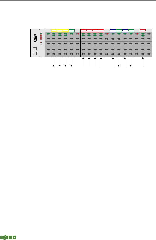
The allocation should become clear by way of a fieldbus node with a coupler and 17 I/O modules.
1 |
2 |
3 |
4 |
5 |
6 |
7 |
8 |
9 |
10 |
11 |
12 |
13 |
14 |
15 |
16 |
17 |
DI DI |
DI DI |
DI DI |
AI AI |
DO DO DO DO DO DO DO DO |
AO AO |
AI AI |
AO AO AI AI |
DO DO |
750-333
402 |
402 |
402 |
452 |
602 |
504 |
504 |
504 |
504 |
602 |
550 |
452 |
550 |
452 |
602 |
504 |
600 |
Fig. 3-9: Example application
PROFIBUS
g012115x
No. |
I/O modules |
Modul |
PI Master * |
|
|
|
Identification |
|
|
|
|
Inputs |
Outputs |
|
|
|
|
||
1 |
Digital input |
750-402 4 DI/24 V DC/3.0 ms |
EB12.0 |
|
|
|
|
|
|
|
Digital input |
0x10 |
EB12.1 |
|
|
|
|
|
|
|
Digital input |
|
EB12.2 |
|
|
|
|
|
|
|
Digital input |
|
EB12.3 |
|
|
|
|
|
|
2 |
Digital input |
*750-402 4 DI/24 V DC/3.0 ms |
EB12.4 |
|
|
|
|
|
|
|
Digital input |
0x00 |
EB12.5 |
|
|
|
|
|
|
|
Digital input |
|
EB12.6 |
|
|
|
|
|
|
|
Digital input |
|
EB12.7 |
|
|
|
|
|
|
3 |
Digital input |
750-402 4 DI/24 V DC/3.0 ms |
EB13.0 |
|
|
|
|
|
|
|
Digital input |
0x10 |
EB13.1 |
|
|
|
|
|
|
|
Digital input |
|
EB13.2 |
|
|
|
|
|
|
|
Digital input |
|
EB13.3 |
|
|
|
|
|
|
4 |
Analog input |
750-452 2 AI/0-20 mA/diff. |
EW0 |
|
|
|
|
|
|
|
Analog input |
0x51 |
EW2 |
|
|
|
|
|
|
5 |
Potential supply |
Potential supply |
--- |
--- |
|
|
|
|
|
6 |
Digital output |
750-504 4 DO/24 V DC/0.5 A |
|
AB8.0 |
|
|
|
|
|
|
Digital output |
0x20 |
|
AB8.1 |
|
|
|
|
|
|
Digital output |
|
|
AB8.2 |
|
|
|
|
|
|
Digital output |
|
|
AB8.3 |
|
|
|
|
|
7 |
Digital output |
*750-504 4 DO/24 V DC/0.5 A |
|
AB8.4 |
|
|
|
|
|
|
Digital output |
0x00 |
|
AB8.5 |
|
|
|
|
|
|
Digital output |
|
|
AB8.6 |
|
|
|
|
|
|
Digital output |
|
|
AB8.7 |
|
|
|
|
|
D R A F T |
WAGO-I/O-SYSTEM 750 |
2001-02-27 |
PROFIBUS |

|
|
|
Fieldbus coupler / controller |
• 35 |
||||
|
|
|
Fieldbus coupler 750-333 |
|
|
|
||
|
|
|
|
|
|
|
|
|
|
|
|
|
|
|
|
|
|
|
8 |
Digital output |
750-504 4 DO/24 V DC/0.5 A |
|
AB9.0 |
|
|
|
|
|
|
|
|
|
|
|
|
|
|
Digital output |
0x20 |
|
AB9.1 |
|
|
|
|
|
|
|
|
|
|
|
|
|
|
Digital output |
|
|
AB9.2 |
|
|
|
|
|
|
|
|
|
|
|
|
|
|
Digital output |
|
|
AB9.3 |
|
|
|
|
|
|
|
|
|
|
|
|
|
9 |
Digital output |
*750-504 4 DO/24 V DC/0.5 A |
|
AB9.4 |
|
|
|
|
|
|
|
|
|
|
|
|
|
|
Digital output |
0x00 |
|
AB9.5 |
|
|
|
|
|
|
|
|
|
|
|
|
|
|
Digital output |
|
|
AB9.6 |
|
|
|
|
|
|
|
|
|
|
|
|
|
|
Digital output |
|
|
AB9.7 |
|
|
|
|
|
|
|
|
|
|
|
|
|
10 |
Potential supply |
Potential supply |
--- |
--- |
|
|
|
|
|
|
|
|
|
|
|
|
|
11 |
Analog output |
750-550 2 AO/0-10 V |
|
AW0 |
|
|
|
|
|
|
|
|
|
|
|
|
|
|
Analog output |
0x61 |
|
AW2 |
|
|
|
|
|
|
|
|
|
|
|
|
|
12 |
Analog input |
750-452 2 AI/0-20 mA/diff. |
EW4 |
|
|
|
|
|
|
|
|
|
|
|
|
|
|
|
Analog input |
0x51 |
EW6 |
|
|
|
|
|
|
|
|
|
|
|
|
|
|
13 |
Analog output |
750-550 2 AO/0-10 V |
|
AW4 |
|
|
|
|
|
|
|
|
|
|
|
|
|
|
Analog output |
0x61 |
|
AW6 |
|
|
|
|
|
|
|
|
|
|
|
|
|
14 |
Analog input |
750-452 2 AI/0-20 mA/diff. |
EW8 |
|
|
|
|
|
|
|
|
|
|
|
|
|
|
|
Analog input |
0x51 |
EW10 |
|
|
|
|
|
|
|
|
|
|
|
|
|
|
15 |
Potential supply |
Potential supply |
--- |
--- |
|
|
|
|
|
|
|
|
|
|
|
|
|
16 |
Digital output |
750-504 4 DO/24 V DC/0.5 A |
|
AB10.0 |
|
|
|
|
|
|
|
|
|
|
|
|
|
|
Digital output |
0x20 |
|
AB10.1 |
|
|
|
|
|
|
|
|
|
|
|
|
|
|
Digital output |
|
|
AB10.2 |
|
|
|
|
|
|
|
|
|
|
|
|
|
|
Digital output |
|
|
AB10.3 |
|
|
|
|
|
|
|
|
|
|
|
|
|
17 |
End module |
End module |
--- |
--- |
|
|
|
* The master addresses listed in the table correspond to the allocation of the process data given in the master configuration.
WAGO-I/O-SYSTEM 750 |
D R A F T |
PROFIBUS |
2001-02-27 |

36 • Fieldbus coupler / controller
Fieldbus coupler 750-333
3.1.6Parameterising the coupler
Before a data exchange is possible between the master and slaves a parameterisation is necessary in addition to the configuration.
The extended parameters (extended User_Prm_Data) is available as a selectable text in the configuration programs using the GSD files.
Description |
Value |
Meaning |
Restart the internal bus after a |
|
Restart of the internal bus following a fault, |
fault |
POWER ON RESET*) |
such as missing termination module, |
|
after interruption of the I/O module supply |
|
|
AUTORESET |
immediately after overcoming I/O module fault |
I/O module diagnosis |
|
The diagnosis information about all diagnosis |
|
|
capable I/O modules, with which the diagnosis |
|
released*) |
is released are |
|
transferred to PROFIBUS-DP master |
|
|
lock |
not transferred to PROFIBUS-DP master |
Process value display |
|
Word or double word orientated process data is |
|
|
transferred to the PROFIBUS-DP master in: |
|
INTEL |
„Little Endian Format“ |
|
MOTOROLA*) |
„Big Endian Format“ |
Behaviour in case of a |
|
In the case of a fault with the PROFIBUS DP |
PROFIBUS DP fault |
|
communication the status of the inserted output |
|
|
periphery can be influenced in various manners: |
|
Stop internal bus transmis- |
the process data exchange of the internal bus is |
|
sion |
stopped, all outputs drop out after a module |
|
|
specific monitoring time of 100 ms |
|
Set start image to zero |
all outputs are reset immediately |
|
Freeze starting image |
all outputs contain the last status before the |
|
Write substitute values*) |
fault |
|
all outputs switch a parameter substitute value |
|
Reaction to internal bus faults |
|
In the case of a fault with the internal commu- |
|
|
nication between the fieldbus coupler and I/O |
|
|
modules, such as, for example: no termination |
|
|
module, |
|
Stop PROFIBUS data |
the data exchange with the PROFIBUS master |
|
exchange*) |
is stopped. |
|
Set start image to zero |
the input information is set to zero |
|
Freeze starting image |
the input information before the fault is main- |
|
|
tained |
|
*) Default settings |
|
D R A F T |
WAGO-I/O-SYSTEM 750 |
2001-02-27 |
PROFIBUS |