Материал: part17

Внимание! Если размещение файла нарушает Ваши авторские права, то обязательно сообщите нам

DICOM PS3.17 2020a - Explanatory Information​

Page 511​


Waveform 1


ECG


time


Synchronization


channel


ECG


Acquisition


Time


Image 1


Image 2


Image 3


time

IMAGES


Image 1


Image 2


Image 3


Acquisition Time


Acquisition Time

Acquisition Time

CLOCK

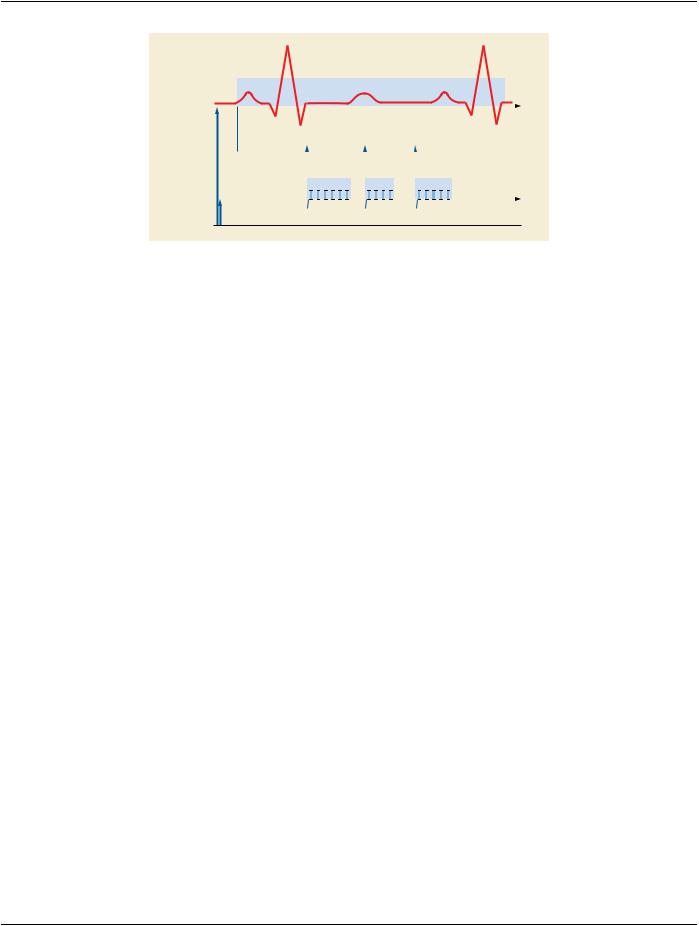
Figure FFF.2.1-10. Example of Image Modality as Source of Trigger​

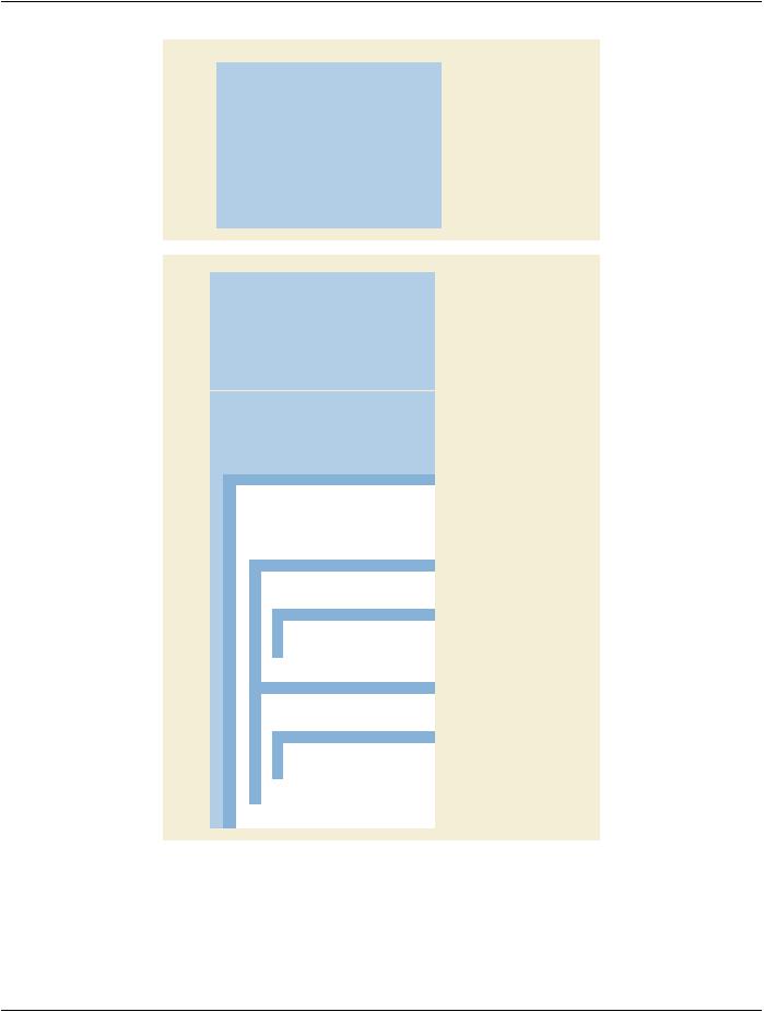
The Attributes that define the relevant content in the two different SOP Instances (Enhanced XA and General ECG) are described in​ Figure FFF.2.1-11.​

- Standard -​

Page 512​

DICOM PS3.17 2020a - Explanatory Information​


Enhanced XA SOP Instance


= UID “A”


Study Instance UID

(0020,000D)


...


Series Instance UID

(0020,000E)

= UID “B”


Modality

(0008,0060)


= XA


...


Synchronization Frame of Reference UID

(0020,0200)


= 1.2.840.10008.15.1.1


Synchronization Trigger

(0018,106A)

= SOURCE


Trigger Source or Type

(0018,1061)


= Imaging System ID


Acquisition Time Synchronized

(0008,1800)


= Y


Time Source

(0018,1801)


= Clock System ID


Time Distribution Protocol

(0018,1802)


= NTP


NTP Source Address

(0018,1803)


= aaa.bbb.ccc.ddd


...


SOP Instance UID

(0008,0018)


= UID “D1”, “D2”, and “D3” resp.


General ECG SOP Instance


Study Instance UID

(0020,000D)


= UID “E”


...


Series Instance UID

(0020,000E)


= UID “F”


Modality

(0008,0060)


= ECG


...


Synchronization Frame of Reference UID

(0020,0200)


= 1.2.840.10008.5.15.1.1

Synchronization Trigger

(0018,106A)


= EXTERNAL

Trigger Source or Type

(0008,1061)


= Imaging System ID

Synchronization Channel

(0008,106C)


= 1/2

Acquisition Time Synchronized

(0008,1800)


= Y

Time Source

(0008,1801)


= Clock System ID

Time Distribution Protocol

(0008,1802)


= NTP

NTP Source Address

(0008,1803)


= aaa.bbb.ccc.ddd

...


SOP Instance UID

(0008,0018)


UID “H”

...


Waveform Sequence

(5400,0100)


Item 1


Only one ECG Multiplex Group


>Multiplex Group Time Offset

(0018,1068)


= 0


= ORIGINAL


>Waveform Originality

(003A,0004)


= 2


>Number of Waveform Channels

(003A,0005)


= 1500


>Number of Waveform Samples

(003A,0010)


= 300


>Sampling Frequency

(003A,001A)


>Channel Definition Sequence

(003A,0200)


First ECG Channel


Item 1


= 1


>>Waveform Channel Number

(003A,0202)


= ECG Recording 1


>>Channel Label

(003A,0203)


>>Channel Source Sequence

(003A,0208)


Item 1


= 2:1


>>Code Value

(0008,0100)


= MDC


>>Coding Scheme Description

(0008,0102)


= Lead I


>>Code Meaning

(0008,0104)


= 0.0


>>Channel Time Skew

(003A,0214)


= 16


>>Waveform Bits Stored

(003A,021A)


Item 2


= 2


>>Waveform Channel Number

(003A,0202)


= Synchronization


>>Channel Label

(003A,0203)


>>Channel Source Sequence

(003A,0208)


Item 1


= 109005


>>Code Value

(0008,0100)


= DCM


>>Coding Scheme Description

(0008,0102)


= X-Ray On Trigger


>>Code Meaning

(0008,0104)


>>Channel Time Skew

(003A,0214)


= 0.0


>>Waveform Bits Stored

(003A,021A)


= 16


>Waveform Bits Allocated

(5400,1004)


= 16


>Waveform Sample Interpretation

(5400,1006)


= SS


Figure FFF.2.1-11. Attributes when Image Modality is the Source of Trigger​

FFF.2.1.2.2.4.2 Waveform modality sends trigger to the image modality​

In this example, there are two modalities that are synchronized with an external clock via NTP.​

- Standard -​

DICOM PS3.17 2020a - Explanatory Information​

Page 513​

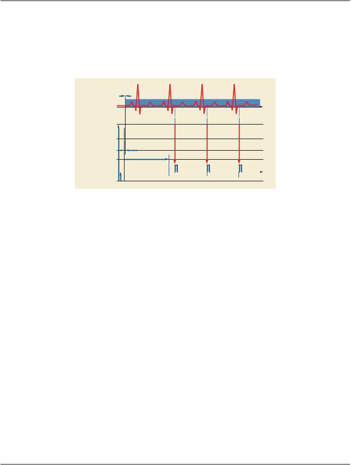
The Image Modality starts the X-Ray image acquisition and simultaneously the Waveform Modality acquires the ECG and analyzes​ the signal to determine the phases of the cardiac cycles. At each cycle, the waveform modality sends a trigger to the image modality​ to start the acquisition of a frame. This trigger is stored in one channel of the waveform modality, together with the ECG signal.​

The ECG sampling frequency is 300 Hz on 16 bits signed encoding, making up a number of 1500 samples per channel. The first​ ECG sample is acquired 10 ms after the nominal start time of the ECG acquisition.​

In this example, there is no UID referencing capability between the two modalities.​


3.3ms

ECG Lead II

time

Synchronization

channel

Nominal start time of

ECG Acquisition Time

Triggers

10ms

Start ECG sampling

Start time of

Image Acquisition

IMAGES


time

Image Acquisition Time


Frame Time

CLOCK

Figure FFF.2.1-12. Example of Waveform Modality as Source of Trigger​

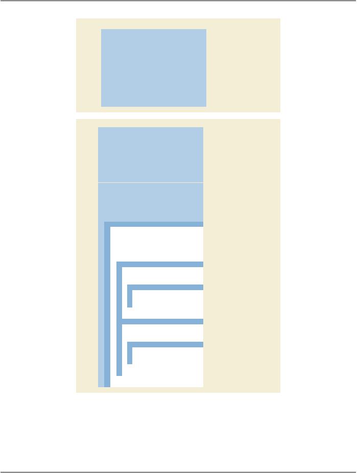
The Attributes that define the relevant content in the two different SOP Instances (Enhanced XA and General ECG) are described in​ Figure FFF.2.1-13.​

- Standard -​

Page 514​

DICOM PS3.17 2020a - Explanatory Information​


Enhanced XA SOP Instance


= UID “A”


Study Instance UID

(0020,000D)


...


Series Instance UID

(0020,000E)

= UID “B”


Modality

(0008,0060)


= XA


...


Synchronization Frame of Reference UID

(0020,0200)


= 1.2.840.10008.15.1.1


Synchronization Trigger

(0018,106A)

= EXTERNAL


Trigger Source or Type

(0018,1061)


= ECG Equipment ID


Acquisition Time Synchronized

(0008,1800)


= Y


Time Source

(0018,1801)


= Clock System ID


Time Distribution Protocol

(0018,1802)


= NTP


NTP Source Address

(0018,1803)


= aaa.bbb.ccc.ddd


...


SOP Instance UID

(0008,0018)


= UID “D”


General ECG SOP Instance


Study Instance UID

(0020,000D)


= UID “E”


...


Series Instance UID

(0020,000E)


= UID “F”


Modality

(0008,0060)


= ECG


...


Synchronization Frame of Reference UID

(0020,0200)


= 1.2.840.10008.5.15.1.1

Synchronization Trigger

(0018,106A)


= SOURCE

Trigger Source or Type

(0008,1061)


= ECG Equipment ID

Synchronization Channel

(0008,106C)


= 1/2

Acquisition Time Synchronized

(0008,1800)


= Y

Time Source

(0008,1801)


= Clock System ID

Time Distribution Protocol

(0008,1802)


= NTP

NTP Source Address

(0008,1803)


= aaa.bbb.ccc.ddd

...


SOP Instance UID

(0008,0018)


UID “H”

...


Waveform Sequence

(5400,0100)


Item 1


Only one ECG Multiplex Group


>Multiplex Group Time Offset

(0018,1068)


= 10


= ORIGINAL


>Waveform Originality

(003A,0004)


= 2


>Number of Waveform Channels

(003A,0005)


= 1500


>Number of Waveform Samples

(003A,0010)


= 300


>Sampling Frequency

(003A,001A)


>Channel Definition Sequence

(003A,0200)


First ECG Channel


Item 1


= 1


>>Waveform Channel Number

(003A,0202)


= ECG Recording 1


>>Channel Label

(003A,0203)


>>Channel Source Sequence

(003A,0208)


Item 1


= 2:2


>>Code Value

(0008,0100)


= MDC


>>Coding Scheme Description

(0008,0102)


= Lead II


>>Code Meaning

(0008,0104)


= 0.0


>>Channel Time Skew

(003A,0214)


= 16


>>Waveform Bits Stored

(003A,021A)


Item 2


= 2


>>Waveform Channel Number

(003A,0202)


= Synchronization


>>Channel Label

(003A,0203)


>>Channel Source Sequence

(003A,0208)


Item 1


= 109002


>>Code Value

(0008,0100)


= DCM


>>Coding Scheme Description

(0008,0102)


= ECG-based gating signal, processed


>>Code Meaning

(0008,0104)


>>Channel Time Skew

(003A,0214)


= 0.0


>>Waveform Bits Stored

(003A,021A)


= 16


>Waveform Bits Allocated

(5400,1004)


= 16


>Waveform Sample Interpretation

(5400,1006)


= SS


Figure FFF.2.1-13. Attributes when Waveform Modality is the Source of Trigger​

- Standard -​

DICOM PS3.17 2020a - Explanatory Information​

Page 515​

FFF.2.1.3 Mechanical Movement​

FFF.2.1.3.1 Rotational Acquisition​

This section provides information on the encoding of the movement of the X-Ray Positioner during the acquisition of a rotational an-​ giography.​

The related image presentation parameters of the rotational acquisition that are defined in the Enhanced XA SOP Class, such as the​ mask information of subtracted display, are described in further sections of this annex.​

FFF.2.1.3.1.1 User Scenario​

The Multi-frame Image acquisition is performed during a continuous rotation of the X-Ray Positioner, starting from the initial incidence​ and acquiring frames in a given angular direction at variable angular steps and variable time intervals.​

Typically such rotational acquisition is performed with the purpose of further 3D reconstruction. The rotation axis is not necessarily​ the patient head-feet direction, which may lead to images where the patient is not heads-up oriented.​

There may be one or more rotations of the X-Ray Positioner during the same image acquisition, performed by following different​ patterns, such as:​

•​One rotation for non-subtracted angiography;​

•​Two rotations in the same or in opposite angular directions, for subtracted angiography;​

•​Several rotations at different time intervals for cardiac triggered acquisitions.​

FFF.2.1.3.1.2 Encoding Outline​

The XA SOP Class encodes the absolute positioner angles as the sum of the angle of the first frame and the increments relative to​ the first frame. The Enhanced XA SOP Class encodes per-frame absolute angles.​

In the XA SOP Class, the encoding of the angles is always with respect to the patient, so-called anatomical angles, and the image is​ assumedtobepatient-oriented(i.e.,heads-updisplay).Incaseofpositionerrotationaroundanaxisobliquetothepatient,notaligned​ with the head-feet axis, it is not possible to encode the rotation of the image necessary for 3D reconstruction.​

The Enhanced XA SOP Class encodes the positioner angles with respect to the patient as well as with respect to a fixed coordinate​ system of the equipment.​

FFF.2.1.3.1.3 Encoding Details​

This section provides detailed recommendations of the key Attributes to address this particular scenario.​

Table FFF.2.1-28. Enhanced X-Ray Angiographic Image IOD Modules​

IE​

Module​

PS3.3 Reference​

Usage​

Image​

XA/XRF Acquisition​

C.8.19.3​

Specifies the type of positioner.​

Table FFF.2.1-29. Enhanced XA Image Functional Group Macros​

Functional Group Macro​

PS3.3 Reference​

Usage​

X-Ray Positioner​

C.8.19.6.10​

Specifies the anatomical angles per-frame.​

X-Ray Isocenter Reference System​ C.8.19.6.13​

Specifies the angles of the positioner per-frame in equipment​


coordinates for further applications based on the acquisition​


geometry (e.g., 3D reconstruction, registration…).​

FFF.2.1.3.1.3.1 XA/XRF Acquisition Module Recommendations​

The usage of this module is recommended to define the type of positioner.​

- Standard -​

Источник: https://studfile.net/preview/14585770/