Материал: part17

Внимание! Если размещение файла нарушает Ваши авторские права, то обязательно сообщите нам

DICOM PS3.17 2020a - Explanatory Information​

Page 521​

Positioner Type

(0018,1508)

= CARM

C-Arm Positioner Tabletop Relationship

(0018,9474)

= YES


...


Per-Frame Functional Groups Sequence

(5200,9230)


Frame 1


Item 1


>Table Position Sequence

(0018,9406)


Item 1


= 0.0


>>Table Top Vertical Position

(300A,0128)


= 0.0


>>Table Top Longitudinal Position

(300A,0129)


= 0.0


>>Table Top Lateral Position

(300A,012A)


= 0.0


>>Table Horizontal Rotation Angle

(0018,9469)


= -10.0


>>Table Head Tilt Angle

(0018,9470)


= 0.0


>>Table Cradle Tilt Angle

(0018,9471)


>Isocenter Reference System Sequence

(0018,9462)


Item 1


= 0.0


>>Table X Position to Isocenter

(0018,9466)


= 500.0


>>Table Y Position to Isocenter

(0018,9467)


= 0.0


>>Table Z Position to Isocenter

(0018,9468)


= 0.0


>>Table Horizontal Rotation Angle

(0018,9469)


= -10.0


>>Table Head Tilt Angle

(0018,9470)


>>Table Cradle Tilt Angle

(0018,9471)

= 0.0


...


Frame “N”


Item “N”


>Table Position Sequence

(0018,9406)


Item 1


= 0.0


>>Table Top Vertical Position

(300A,0128)


>>Table Top Longitudinal Position

(300A,0129)

= 0.0


>>Table Top Lateral Position

(300A,012A)

= 1000.0


>>Table Horizontal Rotation Angle

(0018,9469)

= 0.0


>>Table Head Tilt Angle

(0018,9470)

= -10.0


>>Table Cradle Tilt Angle

(0018,9471)

= 0.0


>Isocenter Reference System Sequence

(0018,9462)


Item 1


= 0.0


>>Table X Position to Isocenter

(0018,9466)


= 673.6


>>Table Y Position to Isocenter

(0018,9467)


>>Table Z Position to Isocenter

(0018,9468)

= 984.8


= 0.0


>>Table Horizontal Rotation Angle

(0018,9469)


>>Table Head Tilt Angle

(0018,9470)

= -10.0


>>Table Cradle Tilt Angle

(0018,9471)

= 0.0


...


Figure FFF.2.1-18. Attributes of the X-Ray Table Per Frame on Table Stepping​

FFF.2.1.4 Changes in X-Ray Controls​

FFF.2.1.4.1 Exposure Regulation Control​

This section provides information on the encoding of the "sensitive areas" used for regulation control of the X-Ray generation of an​ image that resulted from applying these X-Rays.​

FFF.2.1.4.1.1 User Scenario​

The user a) takes previous selected regulation settings or b) manually enters regulation settings or c) automatically gets computer-​ calculated regulation settings from requested procedures.​

Acquired images are networked or stored in offline media.​

Laterproblemsofimagequalityaredeterminedanduserwantstocheckforreasonsbyassessingthepositionsofthesensingregions.​

FFF.2.1.4.1.2 Encoding Outline​

TheEnhancedXAIODincludesamoduletosupplyinformationaboutactiveregulationcontrolsensingfields,theirshapeandposition​ relative to the pixel matrix.​

FFF.2.1.4.1.3 Encoding Details​

This section provides detailed recommendations of the key Attributes to address this particular scenario.​

- Standard -​

Page 522​ DICOM PS3.17 2020a - Explanatory Information​

Table FFF.2.1-38. Enhanced XA Image Functional Group Macros​

Functional Group Macro​

PS3.3 Reference​

Usage​

X-Ray Exposure Control Sensing Regions​C.8.19.6.3​

Specifiestheshapeandsizeofthesensingregionsinpixels,​


as well as their position relative to the top left pixel of the​


image.​

FFF.2.1.4.1.3.1 X-Ray Exposure Control Sensing Regions Macro Recommendations​

This macro is recommended to encode details about sensing regions.​

If the position of the sensing regions is fixed during the multi-frame acquisition, the usage of this macro is shared.​

If the position of the sensing regions was changed during the multi-frame acquisition, this macro is encoded per-frame to reflect the​ individual positions.​

Thesamenumberofregionsistypicallyusedforalltheframesoftheimage.Howeveritistechnicallypossibletoactivateordeactivate​ some of the regions during a given range of frames, in which case this macro is encoded per-frame.​

Table FFF.2.1-39. X-Ray Exposure Control Sensing Regions Macro Recommendations​

Attribute Name​

Tag​

Comment​

Exposure Control Sensing Regions Sequence​

(0018,9434)​

As many items as number of regions.​

FFF.2.1.4.1.4 Example​


In this section, two examples are given.​

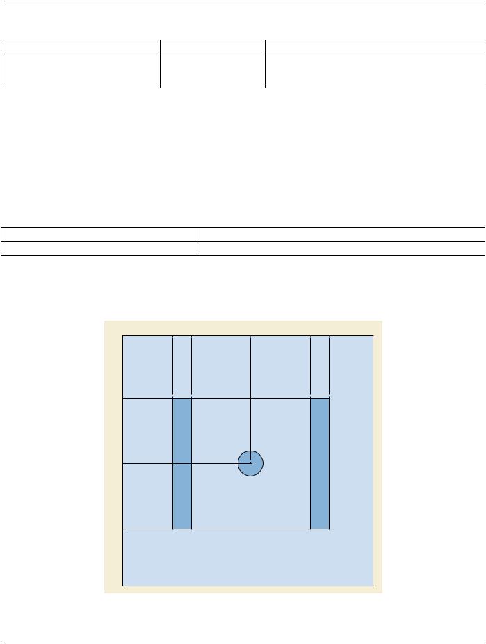
The first example shows how three sensing regions are encoded: 1) central (circular), 2) left (rectangular) and 3) right (rectangular).​

1

200

274

511

750

824

1

250

1

3

2

511

774

Pixel Data Matrix

Figure FFF.2.1-19. Example of X-Ray Exposure Control Sensing Regions inside the Pixel Data matrix​

- Standard -​

DICOM PS3.17 2020a - Explanatory Information​

Page 523​

The encoded values of the key Attributes of this example are shown in Figure FFF.2.1-20.​

...


Shared Functional Groups Sequence

(5200,9229)


All Frames


Item 1


...


Other functional groups


>Exposure Control Sensing Regions Sequence

(0018,9434)


Region 1


Item 1


= CIRCULAR


>>Exposure Control Sensing Region Shape

(0018,9435)


= 511\511


>>Center of Circular Exposure Control Sensing Region

(0018,9440)


= 100


>>Radius of Circular Exposure Control Sensing Region

(0018,9441)


Region 2


Item 2


= RECTANGULAR


>>Exposure Control Sensing Region Shape

(0018,9435)


>>Exposure Control Sensing Region Left Vertical Edge

(0018,9436)

= 200


>>Exposure Control Sensing Region Right Vertical Edge

(0018,9437)

= 274


>>Exposure Control Sensing Region Upper Horizontal Edge

(0018,9438)

= 250


>>Exposure Control Sensing Region Lower Horizontal Edge

(0018,9439)

= 774


Item 3


Region 3


>>Exposure Control Sensing Region Shape

(0018,9435)

= RECTANGULAR


>>Exposure Control Sensing Region Left Vertical Edge

(0018,9436)

= 750


>>Exposure Control Sensing Region Right Vertical Edge

(0018,9437)

= 824


>>Exposure Control Sensing Region Upper Horizontal Edge

(0018,9438)

= 250


>>Exposure Control Sensing Region Lower Horizontal Edge

(0018,9439)

= 774


...


...


Figure FFF.2.1-20. Attributes of the First Example of the X-Ray Exposure Control Sensing Regions​

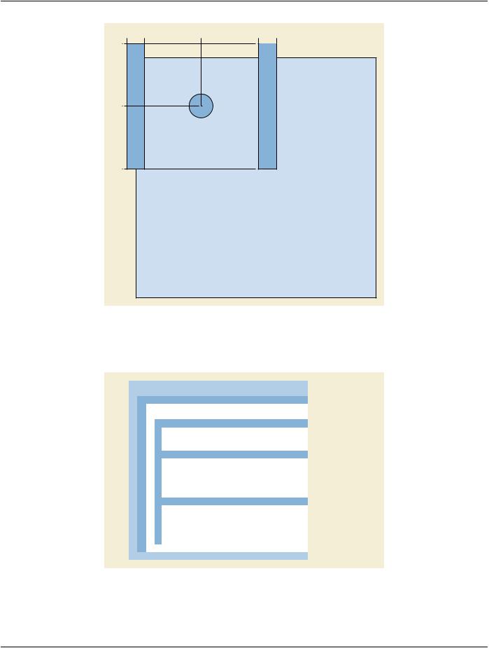
The second example shows the same regions, but the field of view region encoded in the Pixel Data matrix has been shifted of 240​ pixels right and 310 pixels down, thus the left rectangular sensing region is outside the Pixel Data matrix as well as both rectangular​ regions overlap the top row of the image matrix.​

- Standard -​

Page 524​

DICOM PS3.17 2020a - Explanatory Information​

-40 34

271

510 584

-60


1


3


2

201

464

Pixel Data Matrix

Figure FFF.2.1-21. Example of X-Ray Exposure Control Sensing Regions partially outside the Pixel Data​

matrix​

The encoded values of the key Attributes of this example are shown in Figure FFF.2.1-22.​

...


Shared Functional Groups Sequence

(5200,9229)


All Frames


Item 1


...


Other functional groups


>Exposure Control Sensing Regions Sequence

(0018,9434)


Region 1


Item 1


= CIRCULAR


>>Exposure Control Sensing Region Shape

(0018,9435)


= 201\271


>>Center of Circular Exposure Control Sensing Region

(0018,9440)


= 100


>>Radius of Circular Exposure Control Sensing Region

(0018,9441)


Region 2


Item 2


= RECTANGULAR


>>Exposure Control Sensing Region Shape

(0018,9435)


>>Exposure Control Sensing Region Left Vertical Edge

(0018,9436)

= -40


>>Exposure Control Sensing Region Right Vertical Edge

(0018,9437)

= 34


>>Exposure Control Sensing Region Upper Horizontal Edge

(0018,9438)

= -60


>>Exposure Control Sensing Region Lower Horizontal Edge

(0018,9439)

= 464


Item 3


Region 3


>>Exposure Control Sensing Region Shape

(0018,9435)

= RECTANGULAR


>>Exposure Control Sensing Region Left Vertical Edge

(0018,9436)

= 510


>>Exposure Control Sensing Region Right Vertical Edge

(0018,9437)

= 584


>>Exposure Control Sensing Region Upper Horizontal Edge

(0018,9438)

= -60


>>Exposure Control Sensing Region Lower Horizontal Edge

(0018,9439)

= 464


...


...


Figure FFF.2.1-22. Attributes of the Second Example of the X-Ray Exposure Control Sensing Regions​

- Standard -​

DICOM PS3.17 2020a - Explanatory Information​

Page 525​

FFF.2.1.5 Image Detector and Field of View​

ThissectionprovidesinformationontheencodingoftheimagedetectorparametersandfieldofviewappliedduringtheX-Rayacquis-​ ition.​

FFF.2.1.5.1 User Scenario​

The user selects a given size of the field of view before starting the acquisition. This size can be smaller than the size of the Image​ Detector.​

The position of the field of view in the detector area changes during the acquisition in order to focus on an object of interest.​

Acquired image is networked or stored in offline media, then the image is:​

•​Displayed and reviewed in cine mode, and the field of view area needs to be displayed on the viewing screen;​

•​Used for quality assurance, to relate the pixels of the stored image to the detector elements, for instance to understand the image​ artifacts due to detector defects;​

•​Used to measure the dimension of organs or other objects of interest;​

•​Used to determine the position in the 3D space of the projection of the objects of interest.​

FFF.2.1.5.2 Encoding Outline​

The XA SOP Class does not encode some information to fully characterize the geometry of the conic projection acquisition, such as​ the position of the Positioner Isocenter on the FOV area. Indeed, the XA SOP Class assumes that the isocenter is projected in the​ middle of the FOV.​

TheEnhancedXASOPClassencodesthepositionoftheIsocenteronthedetector,aswellasspecificFOVAttributes(origin,rotation,​ flip) per-frame or shared. It encodes some existing Attributes from DX to specify information of the Digital Detector and FOV. It also​ allowsdifferentiatingtheimageintensifiervs.thedigitaldetectorandthendefinesconditionsonAttributesdependingonimageintens-​ ifier or digital detector.​

FFF.2.1.5.3 Encoding Details​

This section provides detailed recommendations of the key Attributes to address this particular scenario.​

Table FFF.2.1-40. Enhanced X-Ray Angiographic Image IOD Modules​

IE​

Module​

PS3.3 Reference​

Usage​

Image​

XA/XRF Acquisition​

C.8.19.3​

Specifies the type of detector.​


X-Ray Image Intensifier​

C.8.19.4​

Conditional to type of detector. Applicable in case of​


IMG_INTENSIFIER.​


X-Ray Detector​

C.8.19.5​

Conditional to type of detector. Applicable in case of​


DIGITAL_DETECTOR.​

Table FFF.2.1-41. Enhanced XA Image Functional Group Macros​

Functional Group Macro​

PS3.3 Reference​

Usage​

X-Ray Field of View​

C.8.19.6.2​

Specifies the field of view.​

XA/XRF Frame Pixel Data Properties​

C.8.19.6.4​

Specifies the Imager Pixel Spacing.​

FFF.2.1.5.3.1 XA/XRF Acquisition Module Recommendations​

The usage of this module is recommended to specify the type and details of the receptor.​

- Standard -​

Источник: https://studfile.net/preview/14585770/