DICOM PS3.17 2020a - Explanatory Information |
Page 527 |
FFF.2.1.5.3.3 X-Ray Detector Module Recommendations
When the X-Ray Receptor Type (0018,9420) equals "DIGITAL_DETECTOR" this module specifies the type and characteristics of the image detector.
The size and pixel spacing of the digital image generated at the output of the digital detector are not necessarily equal to the size and element spacing of the detector matrix. The detector binning is defined as the ratio between the pixel spacing of the detector matrix and the pixel spacing of the digital image.
If the detector binning is higher than 1.0 several elements of the detector matrix contribute to the generation of one single digital pixel.
The digital image may be processed, cropped and resized in order to generate the stored image. The schema below shows these two steps of the modification of the pixel spacing between the detector physical elements and the stored image:
Detector |
|
Detector Reading |
Digital |
|
Field of View Extraction |
|
Stored |
Matrix |
and Binning |
Image |
and Resizing |
|
Image |
Figure FFF.2.1-24. Generation of the Stored Image from the Detector Matrix
Table FFF.2.1-43. X-Ray Detector Module Recommendations
Attribute Name |
Tag |
Comment |
Detector Binning |
(0018,701A) |
The ratio between the pixel spacing of the detector matrix and the pixel |
|
|
spacingofthedigitalimage.Itdoesnotdescribeanyfurtherpost-processing |
|
|
to resize the pixels to generate the stored image. |
Detector Element Spacing |
(0018,7022) |
Pixel spacing of the detector matrix. |
Position of Isocenter Projection |
(0018,9430) |
Relates the position of the detector elements to the isocenter reference |
|
|
system.Itisindependentfromthedetectorbinningandfromthefieldofview |
|
|
origin. |
This Attribute is defined if the Isocenter Reference System Sequence (0018,9462) is present.
FFF.2.1.5.3.4 X-Ray Field of View Macro Recommendations
The usage of this macro is recommended to specify the characteristics of the field of view.
When the field of view characteristics change across the Multi-frame Image, this macro is encoded on a per-frame basis.
The field of view region is defined by a shape, origin and dimension. The region of irradiated pixels corresponds to the interior of the field of view region.
When the X-Ray Receptor Type (0018,9420) equals "IMG_INTENSIFIER", the intensifier TLHC is undefined. Therefore the field of view origin cannot be related to the physical area of the receptor. It is commonly understood that the field of view area corresponds to the intensifier active area, but there is no definition in the DICOM Standard that forces a manufacturer to do so. As a consequence, it is impossible to relate the position of the pixels of the stored area to the isocenter reference system.
Table FFF.2.1-44. X-Ray Field of View Macro Recommendations
Attribute Name |
Tag |
Comment |
Field of View Sequence |
(0018,9432) |
|
>Field of View Shape |
(0018,1147) |
Applicable in this scenario. |
>Field of View Dimension(s) in Float |
(0018,9461) |
Applicable in this scenario. |
>Field of View Origin |
(0018,7030) |
Applicable only in the case of digital detector. |
>Field of View Rotation |
(0018,7032) |
Applicable regardless the type of receptor. |
>Field of View Horizontal Flip |
(0018,7034) |
Applicable regardless the type of receptor. |
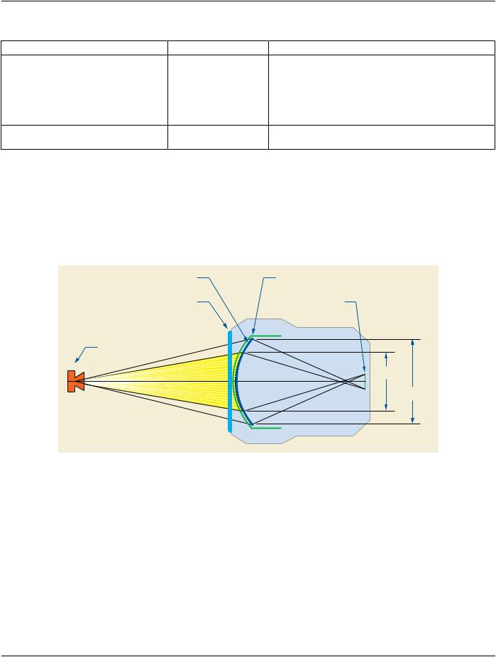



 represent the physical detector pixels;
 represents the TLHC pixel of the physical detector area;
 represents the physical detector pixel in whose center the Isocenter is projected;
 represents the TLHC pixel of the region of the physical detector that is exposed to X-Ray when there is no collimation inside the field of view;
 represents the TLHC pixel of the stored image;
 represents the stored image, which is assumed to be the field of view area. The small thin black straight line squares represent the pixels of the stored image;
 represents Field Of View Origin (0018,7030);
 represents the position of the Isocenter Projection (0018,9430).