Материал: part17

Внимание! Если размещение файла нарушает Ваши авторские права, то обязательно сообщите нам

DICOM PS3.17 2020a - Explanatory Information​

Page 561​

SID = Distance Source to Detector = 1000 mm​

ISO = Distance Source to Isocenter = 800 mm​

Magnification ratio = SID / (ISO - P Yp ) = 1200/(800-68) = 1.366​

Pu = P Xp * Magnification ratio = 142.01 * 1.64 = 194.00 mm​

Pv = P Z p * Magnification ratio = -48.55 * 1.64 = -66.33 mm​

( Pu, Pv)B = (194.00, -66.33) in mm.​

Step 11: Image B: Point (i, j)B in physical detector coordinates​

In this step, the physical detector coordinates (i, j)B are calculated from the positioner coordinates ( Pu, Pv)B by taking into account​ the projection of the Isocenter in physical detector coordinates, and the Detector Element Spacing of the image B:​

ISO_Pidet = Position of Isocenter Projection (column) = 1024.5​

ISO_Pjdet = Position of Isocenter Projection (row) = 1024.5​

Didet =Detector Element Spacing between two adjacent columns = 0.2​

Djdet =Detector Element Spacing between two adjacent rows = 0.2​

i = ISO_Pidet + Pu / Didet = 1024.5 + 194.00 / 0.2 = 1994.5​

j = ISO_Pidet - Pv / Didet = 1024.5 - (-66.33) / 0.2 = 1356.2​

(i, j)B = (1994.5, 1356.2) in detector elements.​

Step 12 : Image B: Point (i, j)B in FOV coordinates​

In this step, the FOV coordinates are calculated from the physical detector coordinates by taking into account the FOV origin and the​ ratio between Imager Pixel Spacing and Detector Element Spacing of the image B:​

Di = Imager Pixel Spacing (column) = 0.4 mm​

Dj = Imager Pixel Spacing (row) = 0.4 mm​

Didet = Detector Element Spacing between two adjacent columns = 0.2 mm​

Djdet = Detector Element Spacing between two adjacent rows = 0.2 mm​

Zoom Factor (column) = Di / Didet = 2.0​

Zoom Factor (row) = Dj / Djdet = 2.0​

FOV Origin (column) = FOVidet = 25.0​

FOV Origin (row) = FOVjdet = 25.0​

new i = (i - FOVidet).Didet / Di - (1 - Didet / Di) / 2 = (1994.5 - 25.0) / 2.0 - 0.25 = 984.5​ new j = (j - FOVjdet).Djdet / Dj - (1 - Djdet / Dj) / 2 = (1356.2 - 25.0) / 2.0 - 0.25 = 665.35​

(i, j)B = (984.50, 665.35) in stored pixel data.​

Step 13 : Image B: Point (i, j)B in Pixel Data​

In this step, the position (i, j)B of the projection of the object of interest in the Pixel Data of the image B is calculated from the FOV​ coordinates by taking into account the FOV rotation and Horizontal Flip applied to the FOV matrix when the Pixel Data were created:​

1.1: Horizontal Flip: NO​

- Standard -​

Page 562​

DICOM PS3.17 2020a - Explanatory Information​

new i = i = 984.50​ new j = j = 665.35​

1.2: Image Rotation: 180 (clockwise)​

new i = (columns -1) - i = 1000 - 1 - 984.50 = 14.50​ new j = (rows -1) - j = 1000 - 1 - 665.35 = 333.65​

(i, j)B = (14.50, 333.65) in stored pixel data.​

- Standard -​

DICOM PS3.17 2020a - Explanatory Information​

Page 563​

GGG Unified Worklist and Procedure Step -​

UPS (Informative)​

GGG.1 Introduction​

ThissectionprovidesexamplesofdifferentimplementationsandmessagesequencingwhenusingtheUnifiedWorklistandProcedure​ Step SOP Classes (UPS Push, UPS Pull, UPS Watch and UPS Event).​

The examples are intended to provide a sense of how the UPS SOP Classes can be used to support a variety of workflow use cases.​ For the detailed specification of how the underlying DIMSE Services function, please refer to Annex CC “Unified Procedure Step​ Service and SOP Classes (Normative)” in PS3.4. For the detailed specification of how the RESTful services function, please refer to​ Section 11.​

TheUnifiedWorklistandProcedureStepServiceClasscombinestheinformationthatisconveyedseparatelybytheModalityWorklist​ and Modality Performed Procedure Step into a single normalized object. This object is created to represent the planned step and​ thenupdatedtoreflectitsprogressfromscheduledtocompleteandrecorddetailsoftheprocedureperformedandtheresultscreated.​ Additionally, the Unified Worklist supports subscription based notifications of progress and completion.​

The Unified Worklist and Modality Procedure Step Service Class does not include support for complex internal task structures. It de-​ scribes a single task to be performed in terms of the task request and the task results. Additional complexity is managed by the​ business logic.​

The UPS SOP Classes define services so UPSs can be created, their status managed, notifications sent and their Attributes set,​ queried, and retrieved. DICOM intentionally leaves open the many combinations in which these services can be implemented and​ applied to enact a variety of approaches to workflow.​

Pull Workflow and Push Workflow​

Similar to previous SOP Classes like Modality Worklist, UPS allows a performing system (using the UPS Pull SOP Class as a C-FIND​ SCU) to query a worklist manager (the SCP) for relevant tasks and choose which one to start working on. This is sometimes called​ "Pull Workflow" since the performer pulls down the list and selects an item.​

UPS adds the ability for a scheduling system (using the UPS Push SOP Class as an N-CREATE SCU) to "push" a workitem onto the​ performing system (here an SCP). In "Push Workflow" the scheduler makes the choice of which system becomes responsible for the​ workitem.​

Performing systems (again as an SCP) could also schedule/create their own workitems, while allowing other systems (using the UPS​ Watch and UPS Event SOP Classes as N-EVENT-REPORT SCUs and N-GET SCUs) to receive notifications of the activities of the​ performer and examine the results.​

Push and Pull can also be combined in various ways. A high level departmental scheduler could break down orders and push tasks​ onto the acquisition worklist manager and reporting worklist manager from which modalities and reporting workstations could pull​ their tasks. In another scenario, a modality that has pulled an acquisition workitem off a worklist, could push a follow-up task onto a​ workstation to perform 3D processing or CAD on the results.​

Reliable Watchers and Deletion Locks​

SomeUPSfeatures(specificallytheDeletionLock-SeeSectionCC.2.3.2,“ServiceClassUserBehavior”)wereintroducedtosupport​ ReliableWatchers.BysubscribingwithaDeletionLock,anSCUwishingtobeareliablewatchercansignaltheSCPtopersistinstances​ until the watcher has been able to retrieve final state information and remove the lock.​

Thismeansthatnetworklatency,slightdelaysinprocessingthreads,oreventhewatcherbeingofflineforashorttime,willnotprevent​ the watcher from reliably collecting the final state details from UPS instances it is interested in. This can be very important since the​ watcher may be responsible for monitoring completion of those instances, extracting details from them, and based on that and other​ internal logic, creating subsequent UPS Instances and populating the input data fields with information from the completed UPS.​ Without some form of persistence guarantee, UPS instances could disappear immediately upon entering a completed state.​

- Standard -​

Page 564​

DICOM PS3.17 2020a - Explanatory Information​

Having established the Deletion Lock mechanism, it is possible that, due to equipment or processing errors, there could be cases​ wherelocksarenotproperlyremovedandsomeUPSinstancesmightremainwhentheyarenolongerneeded.MostSCPimplement-​ ations will likely provide a way for such orphaned UPS instances to be removed under administrator control.​

GGG.2 Implementation Examples​

The following sections describe ways UPS workflows could be used to address some typical scenarios.​

GGG.2.1 Typical SOP Class Implementations​

The decision of which SOP Classes to implement in which systems will revolve partly around where it makes the most sense for the​ business logic to reside, what information each system would have access to, and what kind of workflow is most effective for the​ users.​

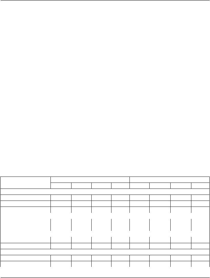
Table GGG.1-1 shows a number of hypothetical systems and the combination of SOP Classes they might implement. For example,​ a typical worklist manager would support all four SOP Classes as an SCP. A typical scheduling system might want to be a UPS Push​ SCU to submit work items to the worklist manager, a UPS Watch SCU to subscribe for notifications and get details of the results, and​ a UPS Event SCU to receive the progress notifications. A simple "pull performer" might only be a UPS Pull SCU, similar to modalities​ today.​

Other examples are listed for:​

•​"Minimal Scheduler", a requesting system that is not interested in monitoring progress or results.​

•​"Watcher", a system interested in tracking the progress and/or results of Unified Procedure Steps.​

•​"General Contractor", a system that accepts work items pushed to it, then uses internal business logic to subdivide/create work​ items that it pushes or makes available to systems that will actually perform the work.​

•​"Push Performer", a system, for example a CAD system, that has work pushed to it, and provides status and results information to​ interested observers.​

•​"Self-Scheduled Performer", which internally schedules it's own work, but supports notifications and N-GET so the details of the​ work can be made available to other departmental systems.​

•​"Self-Scheduled Pull Performer", which pushes a workitem onto a worklist manager and then pulls it off to perform it. This allows​ it to work on "unscheduled" procedures without taking on the responsibility of being an SCP for notifications and events.​

Table GGG.1-1. SOP Classes for Typical Implementation Examples​

SOP Classes​


SCU​


SCP​


UPS Push​UPSWatch​UPS Event​UPS Pull​UPS Push​UPS Watch​UPS Event​UPS Pull​


Non-Performing SCUs​


Minimal Scheduler​

X​


Typical Scheduler​

X​

X​

X​


Watcher​


X​

X​


Worklist SCPs​


Worklist Manager​


X​

X​

X​

X​

General Contractor​

X​

X​

X​

X​

X​

X​

X​


Performing SCPs​


Push Performer​


X​

X​

X​


Self-Scheduled Performer​


X​

X​


Performing SCUs​


Pull Performer​


X​


Self-Scheduled Pull Performer​

X​


X​


- Standard -​

DICOM PS3.17 2020a - Explanatory Information​

Page 565​

A system that implements UPS Watch as an SCP will also need to implement UPS Event as an SCP to be able to send Event Reports​ to the systems from whom it accepts subscriptions.​

GGG.2.2 Typical Pull Workflow​

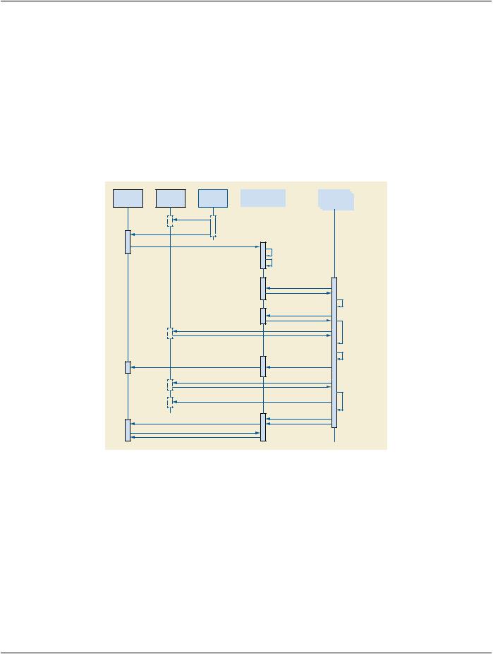
This example shows how a typical pull workflow could be used to manage the work of a 3D Lab. A group of 3D Workstations query​ a 3D Worklist Manager for work items that they perform and report their progress. In this example, the RIS would be a "Typical​ Scheduler", the 3D Workstation is a "Pull Performer" as seen in Table GGG.1-1 and the PACS and Modality do not implement any​ UPS SOP Classes.​

WewillassumetheRISdecideswhichstudiesrequire3Dviewsandputsthemontheworklistoncetheacquiringmodalityhasreported​ it's MPPS complete. The RIS identifies the required 3D views and lists the necessary input objects in the UPS based on the image​ references recorded in the MPPS.​

Assume the RIS has subscribed globally for all UPS instances managed by the 3D Worklist Manager.​

RIS PACS

Acquisition

Modality

Store Images

MPPS Complete

Add UPS Task (N-CREATE)

Query input image instances

Report Task X In-Progress (N-EVENT)

Retrieve input image instances

Store 3D Views

Report Task X Complete (N-EVENT)

Retrieve Final State Details (N-GET)

3D


3D


Worklist Manager


Workstation


Create UPS for Task X

Add RIS to Task X Subscriber List (based on prior Global Subscription)

Query Worklist (C-FIND)

Retrieve full details for

Task X (N-GET)

Claim Task X

(N-ACTION IN-PROGRESS [T-UID])

Record Task Details

(N-SET [T-UID])

Complete Task X

(N-ACTION COMPLETE [T-UID])

Select UPS for Task X

Confirm Availability of Task X inputs

Create

Transaction-UID

Generate 3D Views requested in Task X

Figure GGG.2-1. Diagram of Typical Pull Workflow​

GGG.2.3 Reporting Workflow With "hand-off"​

This example shows a reporting workflow with a "hand-off". Reporting Workstations query a RIS for work items to interpret/report. In​ this example, the RIS is a "Worklist Manager", the Reporting Workstation is both a "Pull Performer" and a "Minimal Scheduler" as​ shown in Table GGG.1-1 and the PACS and Modality do not implement any UPS SOP Classes. A reporting workstation claims Task​ X but can't complete it and "puts it back on the worklist" by canceling Task X and creating Task Y as a replacement, recording Task​ X as the Replaced Procedure Step.​

Assume the RIS is picking up where example GGG.2.2 left off and was waiting for the 3D view generation task to be complete before​ putting the study on the reading worklist. The RIS identifies the necessary input objects in the UPS based on the image references​ recorded in the acquisition MPPS and the 3D UPS.​

- Standard -​

Источник: https://studfile.net/preview/14585770/