Материал: part17

Внимание! Если размещение файла нарушает Ваши авторские права, то обязательно сообщите нам

Page 596​

DICOM PS3.17 2020a - Explanatory Information​

Figure III.3-1. RNFL Example Mapping​

III.4 Diabetic Macular Edema Example​

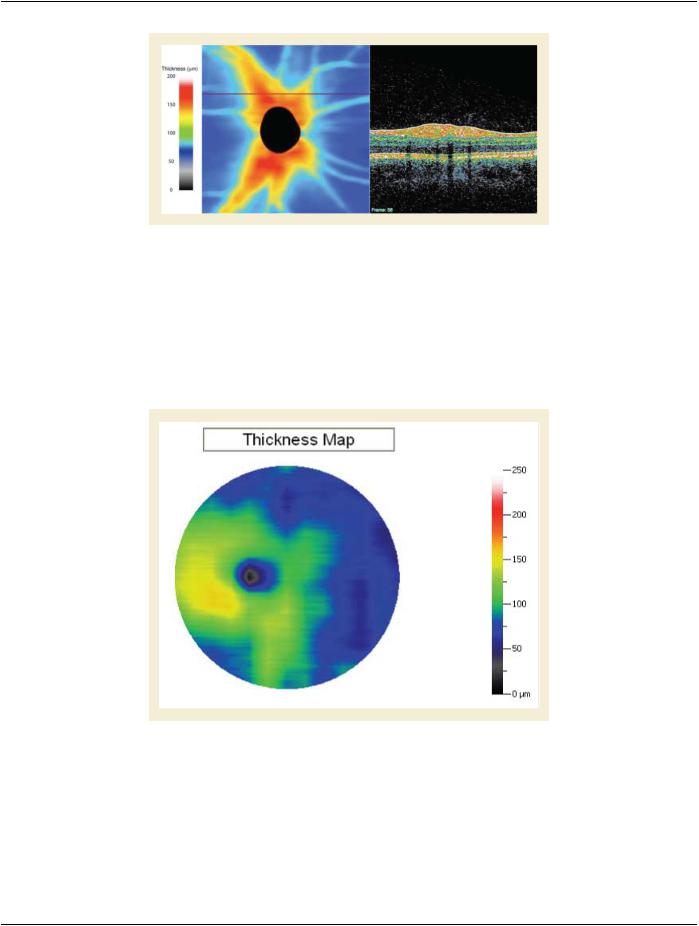
A 48 year old Navajo male with diabetes, decreased visual acuity and fundoscopic stigmata of diabetic retinopathy receives several​ tests to assess his likelihood of macular edema. Optical coherence tomography (OPT) is performed to assess the thickness of the​ retina in the macular area. This is performed with retinal thickness depicted by ophthalmic mapping. The results is an Ophthalmic​ ThicknessMapSOPinstancewiththeOphthalmicThicknessMappingTypeCodeSequence(0022,1436)setto"AbsoluteOphthalmic​ Thickness" and the Measurements Units Code Sequence (0040,08EA) in the Real World Value Mapping Macro, set to "micrometer".​ The OPT image is also referenced in Attribute Referenced Instance Sequence (0008,114A).​

Figure III.4-1. Macula Edema Thickness Map Example​

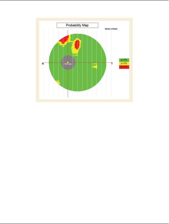
Sincethethicknessofthemaculavariesnormallybaseduponanumberofdependenciessuchasage,gender,race,etc.Interpretation​ of the retinal thickness in any given patient may be done in the context of normative data that accounts for these variables. The​ thickness data used to generate the thickness map is analyzed using a manufacturer specific algorithm for comparison to normative​ data relevant to this specific patient. The results of this analysis is depicted on a second thickness "map" (second SOP Instance)​ showing each pixel's variation from normal in terms of confidence that the variation is real and not due to chance. Specific confidence​ levels are then depicted by arbitrary color mapping registered to the fundus photograph. This is typically noted as the percent probab-​ ility that the variation is abnormal e.g., p >5%, p <5%, p <1% etc. The results is an Ophthalmic Thickness Map SOP instance with the​

- Standard -​

DICOM PS3.17 2020a - Explanatory Information​

Page 597​

OphthalmicThicknessMappingTypeCodeSequence(0022,1436)setto"Thicknessdeviationcategoryfromnormativedata".Mapping​ the "categories" to a code concept is accomplished via Attribute Pixel Value Mapping to Coded Concept Sequence (0022,1450).​

Figure III.4-2. Macula Edema Probability Map Example​

III.5 Glaucoma Example​

A patient was presented with normal visual acuity OU (both eyes), intraocular pressures (IOP) of 18 mm Hg OU (both eyes), and 0.7​ C/D OD (right eye) and 0.6 C/D ratio OS (left eye). Corneal pachymetry showed slight thinning in both eyes at 523µ OD (right eye)​ and 530µ OS (left eye). Static threshold perimetry testing showed nonspecific defects OU (both eyes) and was unreliable due to​ multiple fixation losses. Confocal scanning laser ophthalmoscopy produced OPM topographic representations of both optic nerves​ suggestive of glaucoma. The contouring of the optic nerve head (ONH) in the left eye showed a slightly enlarged cup with diffuse​ thinningofthesuperiorneuralrim.Intherighteye,therewasgreaterenlargementofthecupandslopingofthecupsuperior-temporally​ with a clear notch of the neural rim at the 12:30 position. Corneal compensated scanning laser polarimetry was performed bilaterally.​ Analysis of the OPM representation of the retinal nerve fiber layer (RNFL) thickness map showed moderate retinal nerve fiber loss​ withaccentuationatthesuperiorpolebilaterally.Thepatientwasdiagnosedwithnormaltensionglaucomaandstartedonaglaucoma​ medication. Follow-up examinations showed stable reduction in his IOP to 11 mm Hg OU (both eyes) and no further progression of​ his ONH or RNFL defects.​

III.6 Retinal Thickness Definition​

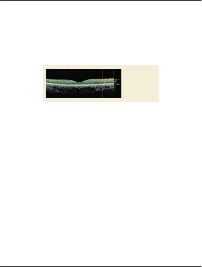
Using OCT technology, there are typically 2 major highly reflective bands generally visible; inner and outer highly reflective bands​ (IHRB and OHRB).​

The inner band corresponds to the inner portion of the retina, which consists of ILM (internal limiting membrane), RNFL (retinal nerve​ fiber layer), GCL (ganglion cell layer), IPL (inner plexiform layer), INL (inner nuclear layer), and OPL (outer plexiform layer). In terms​ of the reflectivity, they present a high-low-high-low-high pattern, in general. Presumably RNFL, IPL, and OPL are the highly reflective​ layers and GCL and INL are of low reflectivity. ILM itself may or may not be visible in OCT images (depending on the scanning beam​ incidence angle), but for convenience it is used to label the vitreo-retinal interface.​

The outer band is considered as the RPE (retinal pigment epithelium) /Choroid complex that consist of portion of photoreceptor, RPE,​ Bruch's membrane, and portion of choroid. Within the RPE/Choroid complex, there are 3 highly reflective interfaces identifiable, pre-​ sumably corresponding to IS/OS (photoreceptor inner/out segment junction), RPE, and Bruch's membrane.​

- Standard -​

Page 598​

DICOM PS3.17 2020a - Explanatory Information​

Clinically 3 retinal thickness measurements are generally acknowledged and utilized; RNFL thickness, GCC (ganglion cell complex)​ thickness, and total retinal thickness.​

RNFLthicknessisdefinedasthedistancebetweenILMandouterinterfaceoftheinnermosthighlyreflectivelayerpresumablyRNFL.​

GCC thickness is defined as the distance between ILM and the outer interface of the second inner highly reflective layer presumably​ the outer border of inner plexiform layer (IPL).​

Total retinal thickness definition varies among OCT manufacturers. The classic definition is the distance between ILM and the first​ highlyreflectiveinterface(presumablyIS-OS)intheOHRB(Totalretinalthickness(ILMtoIS-OS)).Aseconddefinitionisthedistance​ between ILM and the second highly reflective interface (presumably RPE) in the OHRB (Total retinal thickness (ILM to RPE) ). A third​ definition is the distance between ILM and the third highly reflective interface (presumably Bruch's membrane) in the OHRB (Total​ retinal thickness (ILM to BM) ).​

Inner highly-reflective band

Outer highly-reflective band
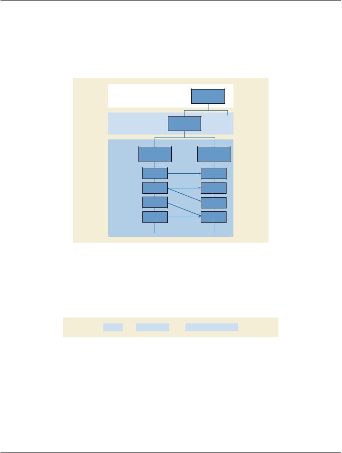
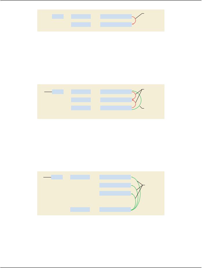
Figure III.6-1. Observable Layer Structures​

III.7 Thickness Calculations Between Various Devices​

Wheninterpretingquantitativedataobtainedfromimagingdevices,comparingmaybeanissue.Usingdifferentdevicesmanufactured​ bydifferentcompaniesusuallyendsupwithnon-comparablemeasurementsbecausetheyusedifferentopticsanddifferentalgorithms​ to make measurements.​

Currently there are multiple SD-OCT devices independently manufactured, and data comparability has become problematic. When​ patients change doctors or otherwise receive care from more than one provider, previously acquired data may occur on different​ devices and become almost useless simply because the present doctor has no access to the same device. Another problem occurs​ with longitudinal assessments on the same device after it has undergone upgrade to a newer generation. In this case new baseline​ measurementsmustbeobtainedduetoincomparabilityofthedata(thishappensevenforthesamemakedifferentgenerationdevices).​ Attempts to normalize the measurements have been unsuccessful.​

Themanufacturer,model,serialnumber,andsoftwareversioninformationareavailableintheEquipmentModule,andisveryimportant​ for considering the significant importance of the information to the quantitative data between various SOP Instances.​

- Standard -​

DICOM PS3.17 2020a - Explanatory Information​

Page 599​

JJJ Optical Surface Scan​

JJJ.1 General Information​

When supporting textures within one acquisition process, multiple series are generated. There is one Series containing the Surfaces​ and another containing the textures. References are used to link Instances in different series together.​

PATIENT


STUDY


SERIES


Surfaces

Textures


Instance


Reference


Instance


Reference


Instance


Reference

Figure JJJ.1-1. Optical Surface Scan Relationships​

JJJ.2 One Single Shot Without Texture Acquisition As Point Cloud​

Use cases: A single surface record of a patient is made, for example teeth, nose, or breast. If third party software does the post-pro-​ cessing only the point cloud needs to be stored.​

The Surface Scan Point Cloud instance will be used because a point cloud is stored. A study with a single series is created.​

Study


Series


Surface Scan Point Cloud


Figure JJJ.2-1. One Single Shot Without Texture Acquisition As Point Cloud​

JJJ.3 One Single Shot With Texture Acquisition As Mesh​

Use cases: A scanner device providing triangulated objects with textures, e.g., for documentation of burns or virtual autopsy.​

The Surface Scan Mesh instance will be used because a triangulated object is stored. A study with two series will be created. One​ series contains a Surface Mesh instance and the other series a VL Photographic Image instance. The latter stores the texture, which​ is mapped on the surface mesh and is linked to the Surface Scan Mesh instance via the UV Mapping Sequence (0080,0008).​

- Standard -​

Page 600​

DICOM PS3.17 2020a - Explanatory Information​


UV Mapping


Study


Series


Surface Scan Mesh


Sequence


Series


VL Photographic Image


Figure JJJ.3-1. One Single Shot With Texture Acquisition As Mesh​

JJJ.4 Storing Modified Point Cloud With Texture As Mesh​

Use cases: The surface of a textured object has been modified, for example artifacts have been manually removed after the study or​ surgery. The new result is stored.​

In the study of the origin Surface Scan Point Cloud instance a Surface Scan Mesh instance is created in its own series containing​ the modified mesh. The Referenced Surface Data Sequence (0080,0013) will be used to reference the original instance. The mesh​ as well as the point cloud points to the texture using the Referenced Surface Data Sequence (0080,0012).​


UV Mapping

Study


Series


Surface Scan Point Cloud

Sequence


Series


VL Photographic Image


Series


Surface Scan Mesh

Referenced


Surface Data


Sequence

Figure JJJ.4-1. Storing Modified Point Cloud With Texture As Mesh​

JJJ.5 Multishot Without Texture As Point Clouds and Merged Mesh​

Use-case: Objects, which need to be scanned from multiple points of view, such as the nose.​

After the acquired point clouds have been merged by a post-processing software application, the calculated surface mesh is stored​ in the same study in a new series. The Referenced Surface Data Sequence (0080,0013) points to all origin Surface Scan Point Cloud​ instances that have been used for reconstruction. The Registration Method Code Sequence (0080,0003) is used to indicate that​ multiple point clouds have been merged.​

Study


Series


Surface Scan Point Cloud


Surface Scan Point Cloud

Referenced


Surface Data


Sequence


Surface Scan Point Cloud


Series


Surface Scan Mesh


Figure JJJ.5-1. Multishot Without Texture As Point Clouds and Merged Mesh​

JJJ.6 Multishot With Two Texture Per Point Cloud​

Use-case: In the application field of dental procedures some products support switching between two different textures for the same​ surface.​

In this case a number of VL Photographic Image instances are stored in the same series.​

- Standard -​

Источник: https://studfile.net/preview/14585770/