DICOM PS3.17 2020a - Explanatory Information |
Page 849 |
JJJJ Multi-energy CT Imaging (Informative)
JJJJ.1 Domain of Application
Multi-energy CT acquires pixel information which correlates to different X-Ray spectra to enable differentiation, quantification and classification of different types of tissues.
To detect the different X-Ray spectra, Multi-energy (ME) CT imaging uses combinations of different Source(s) and Detector(s) tech- nologies such as current switching X-Ray tubes, spectral detectors, multi-layer detectors, multi-source and detector pairs.
JJJJ.2 Use Cases
Multi-energy CT data can be reconstructed and processed in different ways to serve a variety of purposes.
•Differentiate materials that look similar on conventional CT images, e.g., to differentiate Iodine and Calcium in vascular structures or to differentiate vascular structures from adjacent bone.
•Quantifybasematerialstoaccuratelydefinetissuesandorgans.Theintentistoquantifymaterials,andtoextractregionsandorgans based on their composition.
•Generate virtual non-contrast images from a contrast-enhanced image rather than having to scan the patient twice.
•Reduce beam hardening artifacts.
•Enhance the effect of contrast such as highlighting Iodine and soft tissue.
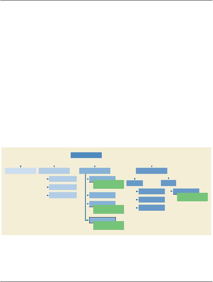
JJJJ.3 Classification of Multi-energy Images
The following Multi-energy image types and families are addressed in this supplement:
|
|
|
|
|
|
|
|
|
|
Multi-Energy Imaging |
|
|
|
|
|
|
|
|
|
|
|
|
|
|
|
|
|
|
|
|
|
|
|
|
|
|
|
|
|
|
|
|
|
|
|
|
|
|
|
|
|
|
|
|
|
|
|
|
|
|
|
|
|
|
|
|
|
|
|
|
|
|
|
|
|
|
|
|
|
|
|
|
|
|
|
|
|
|
|
|
|
|
|
|
|
|
|
|
|
|
|
|
|
|
|
|
|
|
|
|
|
|
|
|
|
|
|
|
|
|
|
|
|
|
|
|
|
|
|
|
|
|
|
|
|
|
|
|
|
|
|
|
|
|
|
|
|
|
|
|
|
|
|
|
|
|
Standard CT Image |
|
Objective Image Family |
|
|
|
Material Quantification Family |
|
|
|
|
|
Material Visualization Family |
|
|
|
|
|
|
|
|
|
|
|
|
|
|
|
|
|
|
|
|
|
|
|
|
|
|
|
|
|
|
|
|
|
|
|
|
|
|
|
|
|
|
|
|
|
|
|
|
|
|
|
|
|
|
|
|
|
|
|
|
|
|
|
|
|
|
|
|
|
|
|
|
|
|
|
|
|
|
|
|
|
|
|
|
|
Virtual Monoenergetic |
|
|
|
|
|
|
Material-Specific Image |
|
|
|
|
|
|
|
|
|
|
|
|
|
|
|
|
|
|
|
|
|
|
|
Image (VMI) |
|
|
|
|
|
|
Examples: |
|
|
|
|
|
|
|
|
|
|
|
|
|
|
|
|
|
|
|
|
|
|
|
|
|
|
|
|
|
|
|
|
|
|
• Iodine Map |
|
Other IOD |
|
|
CT IOD |
|
|
|
|
|
|
|
|
|
Effective Atomic Number |
|
|
|
|
|
|
|
|
|
|
|
|
|
|
|
|
|
|
|
|
|
|
|
|
|
|
|
|
|
|
(Z) Image |
|
|
|
|
|
|
|
• Bone Density |
|
|
|
|
|
|
|
|
|
|
|
|
|
|
|
|
|
|
|
|
|
|
|
|
|
|
|
|
|
|
|
|
|
|
|
|
|
|
|
|
|
|
Color Overlay Image |
|
|
|
|
Material Modified Image |
|
|
|
|
|
|
|
|
Electron Density Image |
|
|
|
|
|
|
Fractional Map Image |
|
|
|
|
|
|
|
|
|
|
|
|
|
|
Examples: |
|
|
|
|
|
|
|
|
|
|
|
|
|
|
|
|
|
|
|
|
|
|
|
|
|
|
|
|
|
|
|
|
|
|
|
|
|
|
|
|
|
|
|
|
|
|
|
|
|
|
|
|
|
|
|
|
|
|
|
|
|
|
|
• Highlighted |
|
|
|
|
|
|
|
|
|
|
|
|
|
|
|
|
|
|
|
|
|
|
|
|
|
Color Blending Image |
|
|
|
|
|
• Partially suppressed |
|
|
|
|
|
|
|
|
|
|
|
|
|
|
|
|
|
|
|
|
|
|
|
|
|
|
|
|
|
|
|
|
|
|
|
|
|
|
|
|
|
|
|
|
|
|
|
|
|
|
Value-based Map Image |
|
|
|
|
|
|
|
|
|
|
|
|
|
|
|
|
|
|
|
|
|
|
|
|
|
|
|
|
|
|
|
|
|
|
|
|
|
|
|
|
|
|
|
|
|
|
|
|
|
|
|
|
|
|
|
|
|
|
|
|
|
|
|
|
|
|
Examples: |
|
|
|
|
|
|
|
|
|
|
|
|
|
|
|
|
|
|
|
|
|
|
|
|
|
|
|
|
|
|
|
|
|
|
|
Color Map Image |
|
|
|
|
|
|
|
|
|
|
|
|
|
|
|
|
|
|
|
|
|
|
|
|
|
|
|
|
|
|
|
|
|
|
|
|
|
|
|
|
|
|
|
|
|
|
|
|
|
|
|
|
|
|
• Gout crystals |
|
|
|
|
|
|
|
|
|
|
|
|
|
|
|
|
|
|
|
|
|
|
|
|
|
|
|
|
|
|
|
|
|
|
• |
|
|
|
|
|
|
|
|
|
|
|
|
|
|
|
|
|
Material Removed Image
Examples:
•Virtual unenhanced (VUE)
•Virtual non-contrast (VNC)
Figure JJJJ.3-1. Classification of Multi-energy Images
Standard CT Image (CT ImageImagescreatedusingMEtechniques,forexample,incaseofthecreationofconventionalappearing IOD, Enhanced CT Image IOD)CT images out of two energy spectra or images created with only one of the multiple energies
acquired. No new image type definitions are needed but new optional Attributes are needed.