Материал: part17

Внимание! Если размещение файла нарушает Ваши авторские права, то обязательно сообщите нам

DICOM PS3.17 2020a - Explanatory Information​

Page 421​

the left side and in the right eye the nasal subfields are on the right side (nasal as determined by the location of the subfield closest​ to the nose).​

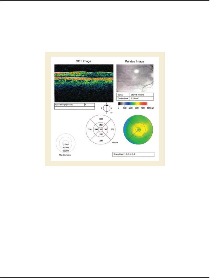
The OPT macula thickness report consists of the thickness at the center point of the grid, and the mean retinal thickness calculated​ for each of the 9 subfields of the grid. In the context of the macular disease considered for the diagnosis, and qualitative interpretation​ of morphology from examination and OPT and/or other modalities, the clinician uses the macula thickness report to determine if the​ center and the grid subfield averages fall outside the normative range. Monitoring of macular disease by serial grid measurements​ allows assessment of disease progression and response to intervention. Serial measurements are assessed by comparing OPT​ thickness or volume reports, provided that the grids are appropriately centered upon the same location in the macula for each visit.​

Figure UU.5-1. Macular Grid Thickness Report Display Example​

The center point of the grid should be aligned with the anatomic center of the macula, the fovea. This can be approximated by having​ thepatientfixateuponatargetcoincidentwiththecenterofthegrid.However,erroneousretinalthicknessmeasurementsareobtained​ when the center of the grid is not aligned with the center of the macula. This may occur in patients with low vision that cannot fixate​ upon the target, or in patients that blink or move fixation during the study. To determine the expected accuracy of inter-visit compar-​ isons, clinicians would benefit from knowing the alignment accuracy of the OPT data from the two visits. Ophthalmologists may also​ want to customize locations on the fundus to be monitored at each visit.​

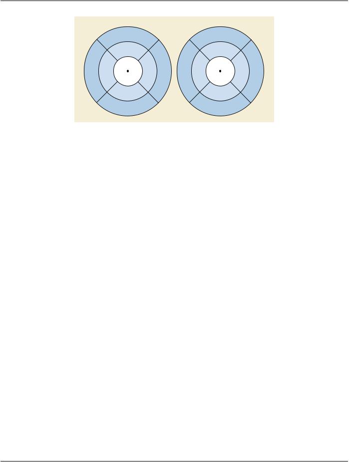
The following figure illustrates how the content items of the Macular Grid Thickness and Volume Report are related to the ETDRS​ Grid. Figure shown is not drawn to scale.​

- Standard -​

Page 422​

DICOM PS3.17 2020a - Explanatory Information​


Right Eye


Left Eye


Outer Superior


Outer Superior


Subfield


Subfield


Inner Superior


Inner Superior


Subfield


Subfield


Center


Center


Outer

Inner

Subfield

Inner

Outer

Outer

Inner

Subfield

Inner

Outer


Temporal Temporal

Center

Nasal

Nasal

Nasal

Nasal

Center

Temporal Temporal

Subfield

Subfield

Subfield

Subfield

Subfield

Subfield

Subfield

Subfield


Point


Point


Inner Inferior


Inner Inferior


Subfield


Subfield


Outer Inferior


Outer Inferior


Subfield


Subfield


Figure UU.5-2. - ETDRS GRID Layout​

UU.6 Interpretation of OPT​

The process of evaluation of diabetic macular edema will help illustrate the role of the OPT macula thickness report. In diabetic​ macular edema there is a breakdown in the blood retina barrier, which can lead to focal and/or diffuse edema (or thickening) of the​ macula. The report of the thickness of each subfield area of the macula grid will help direct treatment. For instance, laser treatment​ to a specific thickened quadrant would be expected to reduce the thickness of retina in the treated zone. Serial comparisons of OPT​ thicknesses should demonstrate a reduction in thickness in the successfully treated zone. A zone that subsequently became thicker​ on follow-up scans may warrant further treatment. In addition to an expected local response to specific zonal treatment such as laser,​ there are treatments with drugs and biologics that are less localized. For instance, the injection of intravitreal drugs in a successfully​ treated eye would be expected to have a global reduction of thickness in all zones with DME. Patients with severe retinal disease​ may lose the ability to fixate making the acquisition of OPT images to represent a specific zone less reliable.​

- Standard -​

DICOM PS3.17 2020a - Explanatory Information​

Page 423​

VV Pediatric, Fetal and Congenital Cardiac​

Ultrasound Reports (Informative)​

VV.1 Content Structure​

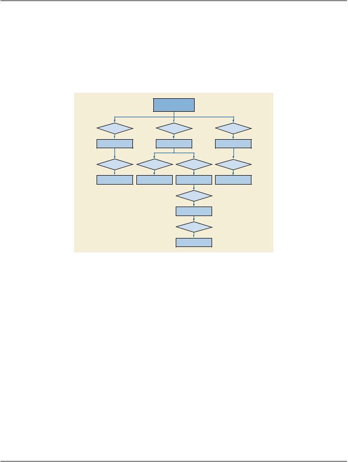
Figure VV.1-1 is an outline of the Pediatric, Fetal and Congenital Cardiac Ultrasound Reports.​

ROOT

Document Title (CONTAINER)

CONTAINS

Patient Characteristics

(CONTAINER)

CONTAINS

Observations

(NUM, CODE)

CONTAINS

Finding (CONTAINER)

HAS CONCEPT MOD

Finding Site

(CODE)

CONTAINS

Measurement Group

(CONTAINER)

CONTAINS

Observations

(NUM)

HAS CONCEPT MOD

CONTAINS

Image Library (CONTAINER)

CONTAINS

Image Entry

(IMAGE)

Target Site

(CODE)

Figure VV.1-1. Top Level Structure of Content​

VV.2 Pediatric, Fetal and Congenital Cardiac Ultrasound Patterns​

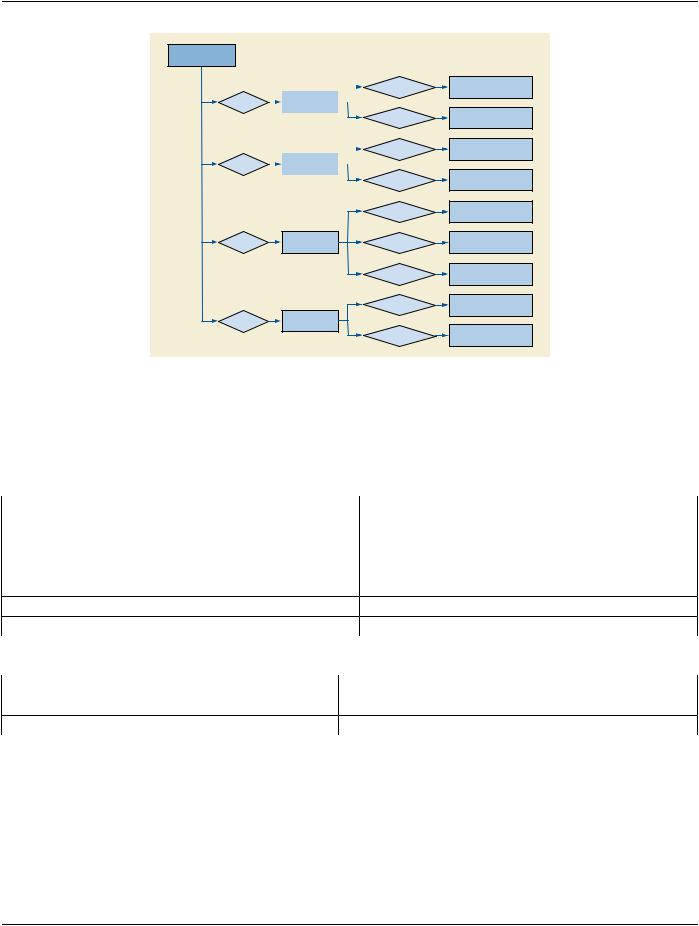
The common Pediatric, Fetal and Congenital Cardiac Ultrasound measurement pattern is a group of measurements obtained in the​ context of a protocol. Figure VV.2-1 shows the pattern.​

- Standard -​

Page 424​

DICOM PS3.17 2020a - Explanatory Information​

Measurement Group

(CONTAINER)


CONTAINS


Internal Dimensions


(NUM)


CONTAINS


A-Wave Duration


(NUM)


CONTAINS

Tissue Velocity

(NUM)


CONTAINS

Cardiac Index

(NUM)


HAS CONCEPT MOD

HAS CONCEPT MOD

HAS CONCEPT MOD

HAS CONCEPT MOD

HAS CONCEPT MOD

HAS CONCEPT MOD

HAS CONCEPT MOD

HAS CONCEPT MOD

HAS CONCEPT MOD

Image Mode =

2D Mode

Cardiac Cycle Point =

End Diastole

Target Site =

Right Superior Pulmonary Vein

Cardiac Cycle Point =

End Systole

Target Site =

Cardiac Valve Annulus

Target Site Modifier =

Medial

Cardiac Cycle Point =

Early Diastole

Measurement Method =

Teichholz

Image Mode =

2D Mode

Figure VV.2-1. Pediatric, Fetal and Congenital Cardiac Ultrasound Measurement Group Example​

VV.3 Measurement Terminology Composition​

Because of the wide variety of congenital issues in fetal and pediatric cardiology, DICOM identifies these findings primarily with post-​ coordination. The concept name of the base content item typically specifies a property, which then requires an anatomic site concept​ modifier.​

Concept Name of Modifier​


Value Set​

(370129005, SCT, "Measurement Method")​

CID 12227 “Echocardiography Measurement Method”​

(363698007, SCT, "Finding Site")​

CID 12280

“Cardiac Ultrasound Target Sites”​

(260674002, SCT, "Flow Direction")​

CID 12221

“Flow Direction”​

(272517003, SCT, "Respiratory Cycle Point")​

CID 12234

“Respiration State”​

(272518008, SCT, "Cardiac Cycle Point")​

CID 12233

“Cardiac Phase”​

(121401, DCM, "Derivation")​

CID 3627 “Measurement Type”​

Further qualification specifies the image mode and the image plane using HAS ACQ CONTEXT with the value sets shown below.​

Concept Name​


Value Set​

(399264008, SCT, "Image Mode")​

CID 12224

“Ultrasound Image Modes”​

(111031, DCM, "Image View")​

CID 12226

“Echocardiography Image View”​

- Standard -​

DICOM PS3.17 2020a - Explanatory Information​

Page 425​

WW Audit Messages (Informative)​

This annex holds examples of audit messaging, as described by the Audit Trail Message Format Secure Use Profile in PS3.15.​

WW.1 Message Example​

An example of one of the DICOM Instances Transferred messages is shown in Example WW.1-1.​

Example WW.1-1. Sample Audit Event Report​

<?xml version="1.0" encoding="UTF-8"?> <AuditMessage

xmlns:xsi="http://www.w3.org/2001/XMLSchema-instance" xsi:noNamespaceSchemaLocation="D:\data\DICOM\security\audit-message.rnc"> <EventIdentification

EventActionCode="C" EventDateTime="2001-12-17T09:30:47" EventOutcomeIndicator="0">

<EventID code="110104" codeSystemName="DCM"

displayName="DICOM Instances Transferred"/> </EventIdentification>

<ActiveParticipant

UserID="123"

AlternativeUserID="AETITLE=AEFOO"

UserIsRequestor="false"

NetworkAccessPointID="192.168.1.2"

NetworkAccessPointTypeCode="2">

<RoleIDCode

code="110153"

codeSystemName="DCM" displayName="Source Role ID"/>

</ActiveParticipant>

<ActiveParticipant

UserID="67562"

AlternativeUserID="AETITLE=AEPACS"

UserIsRequestor="false"

NetworkAccessPointID="192.168.1.5"

NetworkAccessPointTypeCode="2">

<RoleIDCode

code="110152"

codeSystemName="DCM" displayName="Destination Role ID"/>

</ActiveParticipant>

<ActiveParticipant

UserID="smitty@readingroom.hospital.org"

AlternativeUserID="smith@nema" UserName="Dr. Smith" UserIsRequestor="true" NetworkAccessPointID="192.168.1.2" NetworkAccessPointTypeCode="2"> <RoleIDCode
- Standard -​

Источник: https://studfile.net/preview/14585770/