Материал: part17

Внимание! Если размещение файла нарушает Ваши авторские права, то обязательно сообщите нам

Page 436​

DICOM PS3.17 2020a - Explanatory Information​

x x

HPGL Document ID


View Orientation


1


MEDIAL-LATERAL


2


ANTERIOR-POSTERIOR


MATING FEATURE ID: 1


x


2D Mating Feature Coordinates Sequence

x

Referenced HPGL

2D Mating Point


2D Mating Axes


Document ID


1

6.87 / 44.91


1 / 0 / 0 / 1


2

44.24 / 16.7


0.6947 / 0.7193 / -0.7193 / 0.6947


MATING FEATURE ID: 2

2D Mating Feature Coordinates Sequence

Referenced HPGL

2D Mating Point

2D Mating Axes

Document ID


1

6.87 /

44.23

1 / 0 / 0 / 1


2

43.58

/ 16

0.6947 / 0.7193 / -0.7193 / 0.6947


Figure ZZ.1-3. 2D Mating Feature Coordinates Sequence (Example).​

ZZ.1.4 Degrees of Freedom​

For each Item of the Mating Feature Sequence (0068,63E0), degrees of freedom can be specified. A degree of freedom is defined​ by one axis, and can be either rotational or translational. For each 2D and 3D template present, the geometric specifications of the​ mating points can be provided.​

ZZ.1.5 Implant Assembly Templates​

InstancesoftheImplantAssemblyTemplateIODareutilizedtodefineintendedcombinationsofimplanttemplates.AnImplantAssembly​ Template consists of a sequence of component type definitions (Component Type Sequence (0076,0032)) that references Implant​ Template Instances and assigns roles to the referenced implants. In the example in Figure ZZ.1-4, the component types "Stems" and​ "Heads" are defined. Four different stems and two different heads are referenced. Both groups are flagged mandatory and exclusive,​ i.e., a valid assembly requires exactly one representative of each group.​

TheComponentAssemblySequence(0076,0060)declarespossibleconnectionsbetweencomponentsreferencedbythecomponent​ groups.EachsequenceitemreferstoexactlytwoimplanttemplatesthatarepartofatleastonecomponentgroupinthesameImplant​ Assembly Template Instance. An Component Assembly Sequence Item references one mating feature in each of the templates ac-​ cording to which the assembly is geometrically constrained. The double-pointed dashed lines represent the Items of the Component​ Assembly Sequence in Figure ZZ.1-4.​

- Standard -​

DICOM PS3.17 2020a - Explanatory Information​

Page 437​

Component Group 1 “Stems” (Mandatory, Exclusive)

1

x

2

x

3

x

4

x


Component Group 2 “Heads” (Mandatory, Exclusive)

5

6

+

+

Figure ZZ.1-4. Implant Assembly Template (Example)​

ZZ.2 Planning Landmarks​

Registration of implant templates with patient images according to anatomical landmarks is one of the major features of implantation​ planning. For that purpose, geometric features can be attached to Implant Template Instances. Three kinds of landmarks are defined:​ Points, lines, and planes. Each landmark consists of its geometric definition, which is defined per template, and a description.​

WhenregisteringanImplantTemplatetopatientdatalikeanImageoraSurfaceSegmentation,theplanningsoftwareshouldestablish​ a spatial transformation that matches to planning landmarks to corresponding geometric features in the patient data.​

ZZ.3 Implant Registration and Mating Example​

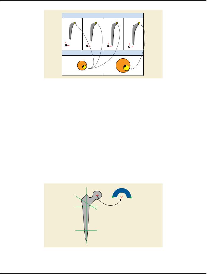
In this section, an example is presented that shows the usage of Implant Templates together with an Implant Assembly Template to​ create an Implantation Plan with patient images. The example is in 2D but can easily be extended to 3D as well. The example looks​ at a simplified case of hip reconstruction planning, using a monoblock stem component and a monoblock cup component.​

Planning consists of 2 steps: Selection and placement of the best fitting cup from the cups referenced by the Assembly Template​ based on the dimension of the patient's hip is the first step. With that done, a stem is selected that can be mated with the selected​ cup and has a neck configuration that leads to an optimal outcome with regard to leg length and other parameters. Therefore, the​ available stems are placed so that the features align. The femoral planning landmarks are used to calculate the displacement of the​ femur this configuration would result in. The workflow is shown in the following set of figures.​

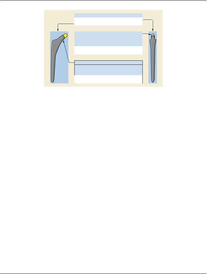
Figure ZZ.3-1. Implant Templates used in the Example.​

- Standard -​

Page 438​

DICOM PS3.17 2020a - Explanatory Information​

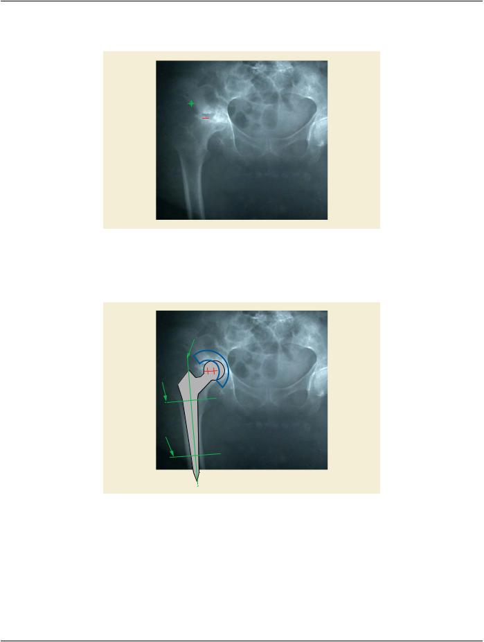
In the first step, the planning landmarks marked with the green arrows in Figure ZZ.3-2 are aligned with compliant positions in the​ patient's x-ray.​

Figure ZZ.3-2. Cup is Aligned with Patient's Acetabulum using 2 Landmarks​

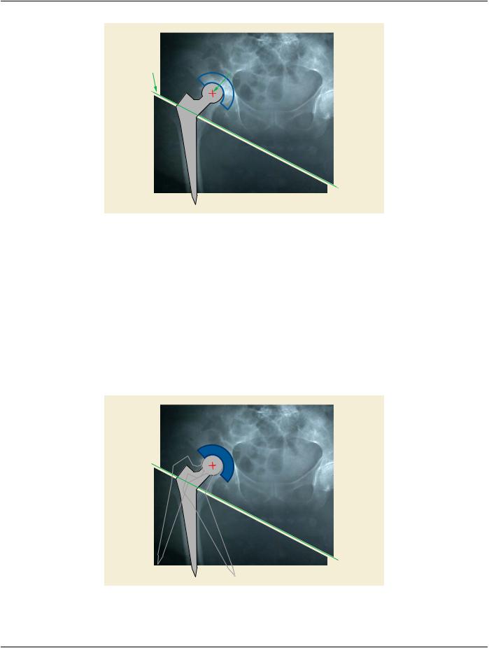
In the second step, the femoral length axis is detected from the patient's x-ray and the stem template is aligned accordingly using the​ femoral axis landmark. The proximal and distal fixation boundary planes are used to determine the insertion depth of the stem along​ that axis.​

Figure ZZ.3-3. Stem is Aligned with Patient's Femur.​

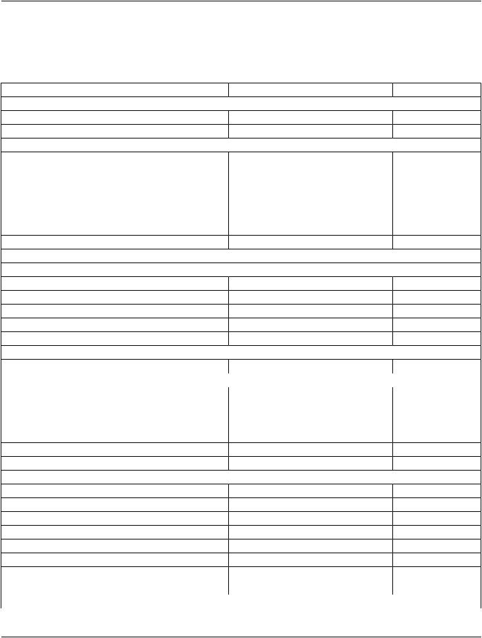
In the third step, the image is split into a femoral and a pelvic part according to the proposed resection plane of the stem template.​ The mating features are used to calculate the spatial relation between the femoral and the pelvic component.​

- Standard -​

DICOM PS3.17 2020a - Explanatory Information​

Page 439​

Figure ZZ.3-4. Femoral and Pelvic Side are Registered.​

ZZ.3.1 Degrees of Freedom​

The hip joint has several degrees of freedom, of course. The Implant Template should contain this information in the Mating Features.​ In the given 2D projections, the rotational freedom of the joint is expressed by one single rotation around the axis of projection inter-​ secting with the printing space at the 2D coordinate of the Mating Feature. Therefore, a Degree Of Freedom Sequence Item added​ to either the stem, the cup, or both.​

In planning, this information could be used to visualize the rotational capacities of the joint after implantation.​

Note​

Technically, the degree of freedom could also have been added to the cup or even (each with half the range of freedom) to​ both. But since we are used to seeing the femur's rotation with respect to the pelvis and not the other way around, it seemed​ natural to do it that way.​

Figure ZZ.3-5. Rotational Degree of Freedom​

- Standard -​

Page 440​

DICOM PS3.17 2020a - Explanatory Information​

ZZ.4 Encoding Example​

The Templates used in the example can be encoded as follows:​

Table ZZ.4-1. Attributes Used to Describe a Mono Stem Implant for Total Hip Replacement​

Attribute​

Value​

Comment​

SOP Common Module​


SOP Class UID​

1.2.840.10008.5.1.4.43.1​


SOP Instance UID​

1.2.3.4.5.6.7.0.1​


Generic Implant Template Module​


Manufacturer​

ACME​


Implant Name​

MONO_STEM​


Implant Size​

MEDIUM​


Implant Part Number​

ACME_MST_M​


Effective DateTime​

26.06.2009 12:00​


Implant Template Version​

1​


Implant Template Type​

ORIGINAL​


Implant Target Anatomy Sequence​


>Anatomic Region Sequence​


>>Code Value​

71341001​


>>Coding Scheme Designator​

SCT​


>>Code Meaning​

Femur​


Frame of Reference UID​

1.2.3.4.5.6.7.1.1​


Overall Template Spatial Tolerance​

1.0​


HPGL Document Sequence​


>HPGL Document ID​

1​


>View Orientation Code Sequence​


>>Code Value​

399348003​


>>Coding Scheme Designator​

SCT​


>>Code Meaning​

Antero-Posterior​


>HPGL Document Scaling​

1.0​


>HPGL Document​

IN PA …​

HPGL commands​

>HPGL Contour Pen Number​

2​


>HPGL Pen Sequence​


>>HPGL Pen Number​

2​


>>HPGL Pen Label​

Contour​


>>HPGL Pen Number​

3​


>>HPGL Pen Label​

Landmarks​


>>HPGL Pen Number​

4​


>>HPGL Pen Label​

Mating Features​


>Recommended Rotation Point​

39.6/72.4​


>Bounding Rectangle​

14.2/5.7/46/78.8​


Material Code Sequence​


- Standard -​

Источник: https://studfile.net/preview/14585770/