Материал: [2.1] 3D Imaging, Analysis and Applications-Springer-Verlag London (2012)
12 |
R. Koch et al. |
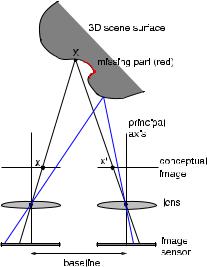
Fig. 1.3 A rectlinear stereo rig. Note the increased image disparity for the near scene point (blue) compared to the far scene point (black). The scene area marked in red can not be imaged by the right camera and is a ‘missing part’ in the reconstructed scene
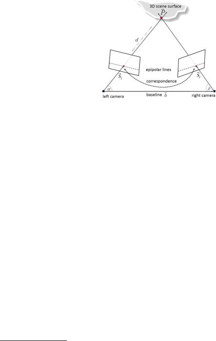
scene surface colored red can not be observed by the right camera, in which case no 3D shape measurement can be made. This scene portion is sometimes referred to as a missing part and is the result of self-occlusion or occlusion by a different foreground object. Image correspondences are found by evaluating image similarities through image feature matching, either locally or globally over the entire image. Problems might occur if the image content does not hold sufficient information for unique correspondences, for example in smooth, textureless regions. Hence, a dense range estimation cannot be guaranteed and, particularly in man-made indoor scenarios, the resulting range images are often sparse. Algorithms, test scenarios and benchmarks for such systems may be found in the Middlebury database [42] and Chap. 2 in this book will discuss these approaches in detail. Note that many stereo rigs turn the cameras towards each other so that they are verged, which increases the overlap between the fields of view of the camera and increases the scene volume over which 3D reconstructions can be made. Such a system is shown in Fig. 1.4.
1.4.2 Active 3D Imaging
Active 3D imaging avoids some of the difficulties of passive techniques by introducing controlled additional information, usually controlled lighting or other electromagnetic radiation, such as infrared. Active stereo systems, for example, have the same underlying triangulation geometry as the above-mentioned passive stereo systems, but they exchange one camera by a projector, which projects a spot or a stripe, or a patterned area that does not repeat itself within some local neighborhood. This latter type of non-scanned system is called a structured light projection. Advances in optoelectronics for the generation of structured light patterns and other
1 Introduction |
13 |
Fig. 1.4 A verged stereo system. Note that this diagram uses a simplified diagrammatic structure seen in much of the literature where only camera centers and conceptual image planes are shown. The intersection of the epipolar plane with the (image) planes defines a pair of epipolar lines. This is discussed in detail in Chap. 2. Figure reprinted from [29] with permission
illumination, accurate mechanical laser scanning control, and high resolution, high sensitivity image sensors have all had their impact on advancing the performance of active 3D imaging.
Note that, in structured light systems, all of the image feature shift that occurs due to depth variations, which causes a change in disparity, appears in the sensor’s one camera, because the projected image pattern is fixed. (Contrast this with a passive binocular stereo system, where the disparity change, in general, is manifested as feature movement across two images.) The projection of a pattern means that smooth, textureless areas of the scene are no longer problematic, allowing dense, uniform reconstructions and the correspondence problem is reduced to finding the known projected pattern. (In the case of a projected spot, the correspondence problem is removed altogether.) In general, the computational burden for generating active range triangulations is relatively light, the resulting range images are mostly dense and reliable, and they can be acquired quickly.
An example of such systems are coded light projectors that use either a timeseries of codes or color codes [8]. A recent example of a successful projection system is the Kinect-camera19 that projects an infrared dot pattern and is able to recover dense range images up to several meters distance at 30 frames per second (fps). One problem with all triangulation-based systems, passive and active, is that depth accuracy depends on the triangulation angle, which means that a large baseline is desirable. On the other hand, with a large baseline, the ‘missing parts’ problem described above is exacerbated, yielding unseen, occluded regions at object boundaries. This is unfortunate, since precise object boundary estimation is important for geometric reconstruction.
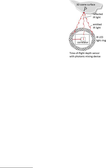
An alternative class of active range sensors that mitigates the occlusion problem are coaxial sensors, which exploit the time-of-flight principle. Here, light is emitted from a light source that is positioned in line with the optical axis of the receiving sensor (for example a camera or photo-diode) and is reflected from the object sur-
19Kinect is a trademark of Microsoft.
14 |
R. Koch et al. |
Fig. 1.5 Active coaxial time-of-flight range estimation by phase shift correlation. Figure reprinted from [29] with permission
face back into the sensor. Figure 1.5 gives a schematic view of an active coaxial range sensor.20 The traveling time delay between outgoing and reflected wave is then measured by phase correlation or direct run-time shuttering, as a direct measure of object distance. Classical examples of such devices are laser-based systems, such as the LIght Detection And Ranging (LIDAR) scanner for long-distance depth estimation. The environment is scanned by deflecting a laser with a rotating mirror and distances are measured pointwise, delivering 3D point clouds. Recently, camera-based receivers are utilized that avoid the need for coherent laser light but use inexpensive LED light sources instead. (Such light sources are also easier to make eye-safe.) Again, the time shift of the reflected light is measured, either by gating very short light pulses directly, or by phase correlation of the time shift between the emitted and reflected light of a modulated continuous LED light source. Such range cameras [44] are depth estimation devices that, in principle, may deliver dense and accurate depth maps in real-time and can be used for depth estimation of dynamic time-varying scenes [31, 32]. Active sensing devices will be discussed in more detail in Chap. 3 and in Chap. 9 in the context of remote sensing.
1.4.3 Passive Stereo Versus Active Stereo Imaging
What are the relative merits of passive and active stereo imaging systems? In summary, since the computational burden of passive correspondences is alleviated, it is generally easier to build active systems that can generate dense range images at high frames rates (e.g. 30 fps for the Kinect). Lack of surface features or sufficiently
20Figures are a preprint from the forthcoming Encyclopedia of Computer Vision [29].

1 Introduction |
15 |
large-scale texture on the scene object can result in passive stereo giving low density 3D reconstructions, at least in the local regions where the surface texture or features (e.g. corners) are missing. This has a number of effects. Firstly, it makes it difficult to comprehensively determine the size and shape of the imaged object. Secondly, it is difficult to get good shape visualizations, when the imaged object is rendered from many different viewpoints. In contrast, as long as the surface is not too dark (low reflectivity) or specular, and does not have too many deep concavities (‘missing parts’), active stereo systems allow comprehensive shape measurements and give good renderings for multi-viewpoint visualizations. Thus, when the density of features is low, or the resolution of image sensing is low compared to the scale of the imaged texture, an active stereo system is the preferred solution. However, the need to scan a laser spot or stripe or to project a structured light pattern brings with it extra complexity and expense, and potential eye-safety issues. The use of spot or stripe scanning also brings with it additional reliability issues associated with moving parts.
There is another side to this discussion, which takes into account the availability of increasingly high resolution CCD/CMOS image sensors. For passive stereo systems, these now allow previously smooth surfaces to appear textured, at the higher resolution scale. A good example is the human face where the random pattern of facial pores can be extracted and hence used to solve the correspondence problem in a passive system. Of course, higher resolution sensors bring with them higher data rates and hence a higher computational burden. Thus, to achieve reasonable realtime performance, improved resolution is developing in tandem with faster processing architectures, such as GPUs, which are starting to have a big impact on dense, real-time passive stereo [56].
1.5 Twelve Milestones in 3D Imaging and Shape Analysis
In the development towards the current state-of-the-art in 3D imaging and analysis systems, we now outline a small selection of scientific and technological milestones. As we have pointed out, there are many historical precursors to this modern subject area, from the ancient Greeks referring to the optical projection of images (Aristotle, circa 350 BC) to Albrecht Duerer’s first mechanical perspective drawing (1525 CE) to Hauck’s establishment of the relationship between projective geometry and photogrammetry (1883 CE). Here, however, we will present a very small selection of relatively modern milestones21 from circa 1970 that are generally thought to fall within the fields of computer vision or computer graphics.
21Twelve milestones is a small number, with the selection somewhat subjective and open to debate. We are merely attempting to give a glimpse of the subject’s development and diversity, not a definitive and comprehensive history.
16 |
R. Koch et al. |
Fig. 1.6 Extracted stripe deformation when scanning a polyhedral object. Figure reprinted from [45] with permission
1.5.1 Active 3D Imaging: An Early Optical Triangulation System
The development of active rangefinders based on optical triangulation appears regularly in the literature from the early 1970s. In 1972, Shirai [45] presented a system that used a stripe projection system and a TV camera to recognize polyhedral objects. The stripe projector is rotated in steps so that a vertical plane of light passes over a polyhedral object of interest. A TV camera captures and stores the deformation of the projected stripe at a set of projection angles, as shown in Fig. 1.6. A set of processing steps enabled shapes to be recognized based on the interrelation of their scene planes. The assumption of polyhedral scene objects reduced the complexity of their processing, which suited the limitations of the available computational power at that time.
1.5.2 Passive 3D Imaging: An Early Stereo System
One of the first computer-based passive stereo systems employed in a clearly defined application was that of Gennery who, in 1977, presented a stereo vision system for an autonomous vehicle [18]. In this work, interest points are extracted and areabased correlation is used to find correspondences across the stereo image pair. The relative pose of the two cameras is computed from these matches, camera distortion is corrected and, finally, 3D points are triangulated from the correspondences. The extracted point cloud is then used in the autonomous vehicle application to distinguish between the ground and objects above the ground surface.
1.5.3 Passive 3D Imaging: The Essential Matrix
When 8 or more image correspondences are given for a stereo pair, captured by cameras with known intrinsic parameters, it is possible to linearly estimate the relative position and orientation (pose) of the two viewpoints from which the two projective