Материал: Russian Journal of Building Construction and Architecture
Issue № 4 (36), 2017 |
ISSN 2542-0526 |
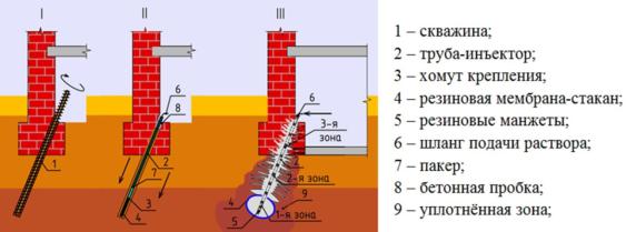
They are all commonly located in the central part of urban construction faced with daunting engineering and geological as well as hydrogeological conditions where pulverescent clayous soil is laid. After comparing existing engineering solutions [3, 4, 6, 7], the authors came up with a new way of laying a drilling injection pile with a controlled widening (Fig. 1) [5].
|
|
|
|
|
|
1 |
–– well |
|
|
|
|
|
|
2 |
–– injection pipe |
|
|
|
|
|
|
3 |
–– mounting collar |
|
|
|
|
|
|
4 |
–– rubber membrane-glass |
|
|
|
|
|
|
5 |
–– rubber cuffs |
|
|
3 |
|
6 –– pipe supplying a solution |
|||
|
|
|
area |
|
|||
|
|
|
|
|
|
7 |
–– packer |
|
|
|
|
8 –– concrete plug |
|||
|
2 area |
||||||
|
|
|
|
|
|
||
|
|
|
|
|
|
9 |
–– consolidated area |
1 area |
|
|
|
||||
|
|
|
|
|
|
|
|
Fig. 1. Scheme of laying a drilling injection pile with a controlled widening:
I — drilling a well; II — assembly of an injection pipe, supply of a packer into the first area of injection holes; III — injection of a solution
The new way combines the advantages of pile and injection methods of strengthening foundations and artificial improvement of construction properties of a soil base by means of a controlled widening, predicted geometric parameters at the end of a pile as well as reinforcement of a soil massive adjacent to a pile using hydrodiscontinuity of a consolidated solution and its consolidation between this discontinuity in the process. A controlled widening was formed during injection of a solution into a membrane-glass insulated on the lower end of the injection pipe [8].
In order to investigate the stress-strain of a foundation massive of the consolidated area for forming a controlled widening series field of studies was carried out to do the following:
1.To determine changes in the initial stress-strain of a foundation massive when a controlled widening is formed with the volume of 30 and 40 liters as well as its partial retention as residual stresses following the injection of a solution;
2.To analyze the results of static tests of the drilling injection piles with a controlled widening andthose without whiledesigning the dependence graphs ofthe pile heaving caused by loading. The field studies were performed in a construction site in the city of Tyumen. The physical and mechanical characteristics of its soil are identified in Table.
51
Russian Journal of Building Construction and Architecture
|
|
|
|
|
|
|
|
Таble |
|
|
|
Physical and mechanical properties of a soil base |
|
|
|||
|
|
|
|
|
|
|
|
|
|
|
Engineering and |
Depth |
Fluidity |
Specific |
Angle of inter- |
Specific |
Deformation |
|
|
weight |
nal friction |
cohesion с, |
modulus Е, |
|||
|
geological element |
Н, m |
index IL |
|||||
|
γ, kN/m3 |
φ, degrees |
kPa |
МPа |
||||
|
|
|
|
|
||||
1 |
|
Semi-solid clay |
0.5—1.4 |
0.15 |
17.9 |
18.1 |
26.0 |
18.7 |
|
|
|
|
|
|
|
|
|
2 |
|
Soft plastic loam |
1.4—6.6 |
0.62 |
19.0 |
16.9 |
21.0 |
7.8 |
|
|
|
|
|
|
|
|
|
1. Determining stresses in the consolidated area at the end of the drill injection pile
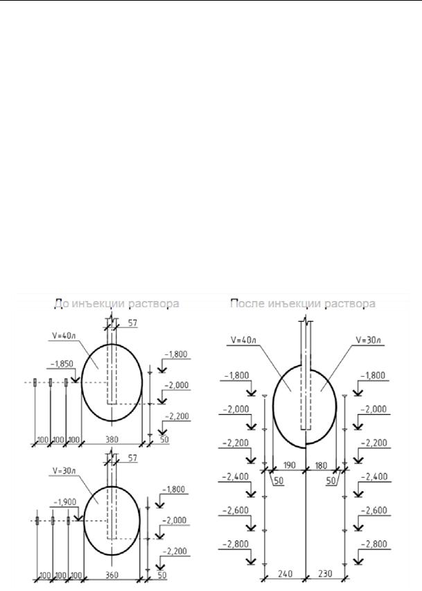
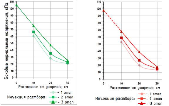
The stress-strain of a soil massive of the consolidated area while a controlled widening was formed was read using angular depth stamps and membrane gauge dynamometers [6] (Fig. 2). According to the depth dynamometers, graphs of changes in normal stresses of a soil massive prior and following the injection of a solution into the membrane glass were shown on a computer screen (Fig. 3—4).
Prior to the injection of a solution |
|
|
Following the injection of a solution |
||
|
|
|
Fig. 2. Scheme of positioning the depth stamps and dynamometers
52
Issue № 4 (36), 2017 |
ISSN 2542-0526 |
а) |
|
b) |
|
Lateral normal stresses, kPa |
Lateral normal stresses, kPa |
|
|
|
|
Distance from a widening, cm |
|
|
|
|
|
|
|
||
|
Distance from a widening, cm |
|
||||||||
|
|
|
|
|
|
|
|
|
|
|
|
|
1 Stage |
|
|
|
|
|
|||
|
|
|
|
|
1 Stage |
|
||||
Injection of a solution: |
|
|
|
|||||||
|
2 Stage |
|
|
|
|
|
||||
Injection of a solution: |
|
2 Stage |
|
|||||||
|
|
|
3 Stage |
|
|
|
|
3 Stage |
|
|
|
|
|
|
|
||||||
|
|
|
|
|
|
|
|
|
|
|
|
|
|
|
|
|
|
|
|
|
|
Fig. 3. Graphs of the distribution of stresses during the injection of a solution into the membrane-glass: а) formation of a controlled widening with the volume of 40 liters; b) 30 liters
All the three graphs almost synchronously show the dynamics of changes in the stresses while a controlled widening is formed in a soil massive. A solution was injected into the membraneglass in three stages with technical breaks of 1 min in order to:
––prevent defects (tear of the membrane wall) during injection of the entire solution volume into the membrane-glass;
––measure the relaxation of momentary stresses of the elastic-plastic state of a soil massive;
––measuretheresidual momentarystressofthe elastic-plasticstate of a soil massive.
Following the formation of a controlled widening at the end of the pile along with a consolidated area of a soil massive, there is a change in the original stress-strain (residual stresses) some of which (the average of up to 43 %) is retained within the consolidated area of a soil massive as residual stresses.
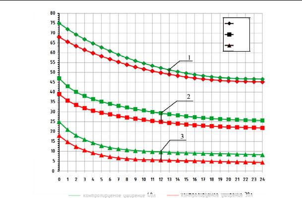
An almost linear character of the graphs of the distribution of stresses at the third stage of injection indicates that residual plastic deformations in the consolidated are selected. Relaxation of stresses in the water-saturated soil massive is due to dissipation of residual pore pressure during filtration consolidation of a pulverescent clayous soil.
53
Russian Journal of Building Construction and Architecture
10 cm
20 cm
30 cm
Lateral normal stresses, kPa
Time, h
Controlled widening of 40 liters |
|
Controlled widening of 30 liters |
|
|
|
Fig. 4. Graphs of relaxation of stresses following the injection of a solution into the membrane-glass in the consolidated area of a controlled widening:
1 —at the distance of 10 cm from the predicted widening diameter; 2 — of 20 cm; 3 — of 30 сm
2. Results of static tests of the drilling injection pile with a controlled widening
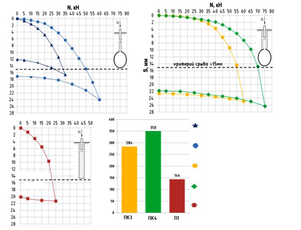
In order to compare the operation of drilling injection piles with a controlled widening with the volume of 30—40 liters and those without, static tests were performed according to the GOST method [1]. As a result, the dependence graphs of the pile heaving on loading were designed with a comparative histogram along the specific bearing capacity (Fig. 5).
Fluent curved lines of the graphs «P3» and «PК4» indicate a slow growth of heaving with two characteristic areas: of the linear operation corresponding with the loading of up to 30—40 kN (VI—VIII) and of the elastic plastic operation corresponding with the loading of up to 50—70 kN (V—VII). For loading that is about half of the bearing capacity of the piles with controlled widenings Fd / 2 up to 30kN (VI), the total heaving was no more than 2 mm, which is particularly important for foundation strengthening through the course of reconstruction.
It should also be noted that curved unloadings of the piles “PK3” and “PK4” (bent lines) are different from the standard form of unloading of a pile [2] with no widening “P1” (a hollow
54
Issue № 4 (36), 2017 |
ISSN 2542-0526 |
line) and are characterized by a maximum bending angle at the initial moment of time, the elastic output is of up to 27 % of the total heaving.
It was also found that the bearing capacity of a pile considering the operation of the tube almost linearly depends on the volume of a widening that is up to two times as large as its value.
Hydro-discontinuity of repeated injection increases the bearing capacity of the pile with a widening by 35—40 %.
S, mm
S, mm
Failure criterion
= 15 mm
Failure criterion
= 15 mm
Specific bearing capacity, kN/m3
mmS, |
|
|
|
|
Failure criterion = 15 mm |
|
|
|
|
|
|
Drilling injection pile with a controlled widening at the end V = 30 liters without the injection of a solution in the hydro-discontinuity mode
Drilling injection pile with a controlled widening at the end V = 40 liters without the injection of a solution in the hydro-discontinuity mode
Drilling injection pile with repeated injection of a solution in the hydro-discontinuity mode and controlled widening at the end V = 30 liters
Drilling injection pile with repeated injection of a solution in the hydro-discontinuity mode and controlled widening at the end V = 40 liters Drilling injection pile with repeated injection of a solution in the hydro-discontinuity mode with no widening at the end
Number of the pile
Fig. 5. Dependence graphs s = f(p)
with a comparative histogram along the specific bearing capacity
In order to determine the geometric parameters of widening, they were excavated (Fig. 6):
––a widening with the volume of 30 liters: d = 340—360 mm, h = 410—430 mm, d/h = 0.8;
––a widening with the volume of 40 liters: d = 370—390 mm, h = 510—530 mm, d/h = 0.7.
55