Материал: Russian Journal of Building Construction and Architecture
Russian Journal of Building Construction and Architecture
b)
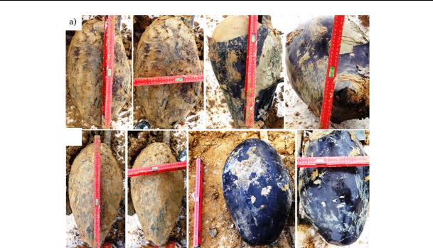
Fig. 6. Geometric parameters of widenings: а) with the volume of 30 liters; b) 40 liters
Conclusions
1.Following the formation of a controlled widening at the end of a pile (unlike other ways of obtaining a widening), there is a consolidated area of a soil massive with an average distribution radius of 0.4—0.6 m from the injection tube and a considerable change in the physical and mechanical characteristics: the density goes up by an average of 25 %; the humidity decreases by 37 %; the deformation modulus increases by 64 %; with the retaining changed initial stress-strain (residual stress) of up to 43 % and linear character of their distribution.
2.The graph of the operation of the piles with a widening under a static compressing load has an initial linear and non-linear (elastic plastic) deformation area. At initial stages of unloading there is an active growth of recurring deformations whose character is fundamentally different from the graph of unloading of regular piles and this is due to the influence of residual stresses in a soil massive while a controlled widening is formed.
3.According to the results of static tests, it was found that a controlled widening at the end of a pile increases its bearing capacity by an average of 2 times due to change in the initial stress-strain of a soil massive in the widening area.
Therefore during loading of a foundation deformation of a base will emerge in the elastic linear stage with a minimum heaving, which is crucial for strengthening foundations as part of reconstruction.
56
Issue № 4 (36), 2017 |
ISSN 2542-0526 |
References
1.GOST 5686-2012. Grunty. Metody polevykh ispytaniy svay [GOST 5686-2012. Soils. Methods of field testing of piles]. Moscow, Minstroy Publ., 1994. 48 p.
2.Konyushkov V. V., Ulitskiy V. M. Otsenka nesushchey sposobnosti buroin"ektsionnykh svay [Evaluation of the bearing capacity of CFA piles]. Vestnik grazhdanskikh inzhenerov, 2007, no. 7, pp. 52—57.
3.Ledenev V. V., Chukanov M. A. Raspredelenie gorizontal'nykh napryazheniy v grunte ot deystviya nagruzki na fundament [Distribution of horizontal stresses in the soil from the action of the load on the Foundation].
Nauchnyy vestnik Voronezhskogo GASU. Stroitel'stvo i arkhitektura, 2011, no. 3, pp. 9—17.
4.Mangushev R. A., Nguen K. Kh. Metodika sostavleniya geotekhnicheskikh kart s uchetom rekomendatsiy po vyboru optimal'nykh tipov fundamentov dlya zdaniy s podzemnym prostranstvom (na primere g. Khoshimina) [Methods of preparing geotechnical maps including recommendations on optimal types of foundations for buildings with underground space (on the example of Ho Chi Minh city)]. Nauchnyy vestnik Voronezhskogo GASU. Stroitel'stvo i arkhitektura, 2008, no. 3, pp. 29—35.
5.Pronozin Ya. A., Zazulya Yu. V., Samokhvalov M. A. Sposob izgotovleniya buroin"ektsionnoy svai s kontroliruemym ushireniem [A method of manufacturing a bored pile with controlled widening]. Patent RF.
6.Petrukhin V. P., Shulyat'ev O. A., Mozgacheva O. A. Novye sposoby geotekhnicheskogo proektirovaniya i stroitel'stva [New methods of geotechnical design and construction]. Moscow, ASV Publ., 2015. 224 p.
7.Pronozin Ya. A., Zazulya Yu. V., Mel'nikov R. V., Stepanov M. A. Opyt sovmestnogo primeneniya in"ektsionnykh svay i kessona pri ustroystve podzemnogo etazha zdaniya istoriko-kul'turnogo naslediya v g. Tobol'ske [Experience of joint use of injection piles and caisson in the device of the underground floor of the building historical-cultural-slide in Tobolsk]. Available at: www.science-education.ru/109-9206
8.Pronozin Ya. A., Samokhvalov M. A., Rachkov D. V. Rezul'taty laboratornykh i polevykh issledovaniy izgotovleniya buroin"ektsionnoy svai s kontroliruemym ushireniem [The results of laboratory and field studies of the manufacture of grout-injected piles controlled broadening]. Promyshlennoe i grazhdanskoe stroitel'stvo, 2014, no. 3, pp. 56—60.
57

Russian Journal of Building Construction and Architecture
HEAT AND GAS SUPPLY,VENTILATION,
AIR CONDITIONING,GAS SUPPLY AND ILLUMINATION
UDC536.491
N. Yu. Saprykina1, P. V. Yakovlev2
INVESTIGATION OF THE FORMATION OF THE TEMPERATURE FIELD OF SOIL DURING THE OPERATION GEOTHERMAL HEAT PUMPS UNDER THE INFLUENCE OF GROUNDWATERS
Astraxan' Institute of Civil Engineering
Russia, Astraxan’, tel.: +7-927-661-48-60, e-mail: nadin_id@rambler.ru 1PhD student of the Dept. of Heat and Gas Supply and Ventilation Astraxan' State Technical University
Russia, Astraxan', tel.: +7-812 61-43-00, e-mail: astu@astu.org 2D. Sc. in Engineering, Prof. of the Dept. of Safety and Hydromechanics
Statement of the problem. Developing long-term forecast of energy efficiency of the heat pump, the characteristics of which vary due to changes in the natural distribution of the temperature field of the Earth in the long life of the well is addressed. Given the fact in most cases there are groundwaters that have an impact on the formation temperature, there is an individual study of the influence of seepage flow in the emerging field of temperature.
Results. The description of the prediction of the thermal field soil mass in operation of geothermal heat pumps in the long-term work under the influence of groundwater is presented.
Conclusions. A temperature field regardless of external factors affecting the well operated — flow filtration of the earth has the properties of «compensation cushion». The temperature of the reservoir that is being stabilized does not allow further «displacement» of the field, which may have a positive effect on the overall operation of the system.
Keywords: heat pump, geothermal wells, temperature field, soil mass, filtration flow, groundwater, filtration rate.
Introduction
A soil body is a complex research object that influences the formation of a temperature field around a geothermal well and the parameters of the operation of pumping equipment. A combination of thermophysical and hydrological processes affect the formation of the temperature
© Saprykina N. Yu., Yakovlev P. V., 2017
58
Issue № 4 (36), 2017 |
ISSN 2542-0526 |
of a soil body [1, 5, 9, 13, 14]. Considering the fact that there is mostly groundwater and they affect the bedding temperature, it is necessary that the effect of filtration flows on a forming temperature field of a soil is evaluated for a heat (drain) source, which is a geothermal well. Design of a temperature field will not be complete [2, 3, 10, 15] unless groundwater, which are in motion, form a filtration flow that also transfers heat is taken into account. This effect can be a key factor in studying a temperature pattern of a soil when geothermal heat pumps are used long-term.
1. Моdeling a temperature field of a soil under the influence of a filtration flow
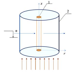
Based on the analysis of the influencing factors and existing research methods for addressing the issue, a mathematical modeling method using a numerical solution was chosen [4]. A motion model of a filtration flow of groundwater is illustrated in Fig. 1.
Fig. 1. Model of calculating a temperature field
H level, G.W. of a soil under the influence of a filtration flow of groundwater:
υ is a filtration rate;
Qbackground is a background flow of the ground; Hlevel. G. W. is a groundwater level;
1 is a geothermal well;
2 is an influence range of a heat flow
Q background
A filtration rate of groundwater near a well is determined with a natural (background) filtration flow that is not influenced by a geothermal well. For most soils Darcy’s law [6] holds true for calculating a filtration rate in a quite wide range of filtration rates:
kФ i , |
(1) |
where υ is a filtration rate, m/seс; kф is a filtration coefficient; i is a hydraulic deviation.
A filtration coefficient for different soils varies in wide ranges [7]. For almost water permeable soils (clay, monolith rocky soils) kф <5·10–5 m/day, quite weakly water permeable (loams, heavy sandy loam, uncrumbling sand grains) kф is up to 5·10–3 m/day, for weakly water permeable (heavy sandy loam, weakly crumbling loamy shale, sandstone, limestone) it is up to
59

Russian Journal of Building Construction and Architecture
0.5 m/day, for water permeable (thinand fine-grained sands, crumbling rock) –– up to 5 m/day, well water permeable (medium-grained sand, permeable (sand medium-grained, highly crumbling rock) — up to 50 m/day, highly water permeable (pebble, gravelly sand, highly crumbling rock) >50 m/day.
A hydraulic deviation depends on hydrogeological features of a region and is largely due to surface drainage. For each region deviations vary. In the Southern Federal District they are different, e.g., the average deviation of the Volga River is 0.00007, or 0.07 ‰; in the Kuban River below the city of Krasnodar it is 0.01 ‰. Precise coefficients of filtration and hydraulic deviation for a certain geothermal well require more in-depth studies.
Due to the complexity of the problem and influencing factors of groundwater, the solution takes two stages: the first one is obtaining the dependence for a complex heat exchange with no filtration influence; the second one is a modified equation with a correction for filtration. In a cylindrical system of coordinates typical of a vertical well, the equation of non-stationary thermal conductivity holds true [4]. Given a natural background flow of the Earth as a compensating correction as well as a convective component, the equation will take the following form:
dt |
( |
dt |
x |
dt |
y dt |
z ) a 2t q , |
(2) |
|
d |
dx |
dy |
||||||
|
|
dz |
|
|
where
dxdt x dydt y dzdt z
–– is a convective component of a change in the temperature; q are sources and drainages of heat that are affected by heat flows of the Earth and heat emission through a surface, Watt/m2; 2 is the Laplacian operator:
2 2t2 y2t2 z2t2 . x
What is particular about the mathematical study is that the initial condition for each new cycle is a temperature field that is retained following the previous cycle. The boundary conditions are divided into three stages. The first stage is when the initial condition is accepted at the moment of the original temperature distribution in the layer prior to the operation of a setup, i.e. this is an even distribution with a background temperature of a layer at all the points. The beginning of the coordinates is at the centre of the well r 0:
t r, t0 , |
(3) |
where r0 is a coordinate ranging from r0 r rк , m.
60