Материал: Russian Journal of Building Construction and Architecture
Issue № 4 (36), 2017 |
ISSN 2542-0526 |
and washing liquids [7]. The passive methods are thermal electric coolers that operate based on the Peltier effect which are not efficient for fairly large thermal emissions in cooled down premises. Ventilation is to be regarded with a certain degree of caution as there might be dust and moisture in the air that might accumulate on the elements of the premises. Liquid cooling systems of semi-conductors are quite effective but inconvenient if cooling is necessary in non-stationary conditions (e.g., tents, on the road, field, etc.).
1. Choosing a method of cooling insulated premises
Lately there has been a lot of focus on indirect water vapor cooling abroad [8—12]. We suggest that an indirect water vapor cooler is used to reduce the temperature in different limited spaces including electronic equipment blocks [5, 6].
An air flow that does not come in contact with moist surfaces of the plates of the cooler by means of using a duct ventilator is run through a cooling object and goes back into the cooler. This flow will be referred to as dry or hot. The air supplied from the environment is cooled down due to water evaporation from moist surfaces of the plates and by means of heat transfer it cools down a dry air flow. This flow will be referred to as wet or cold. It can be released into the external environment and can be used to cool down a premises where a cooling volume is located.
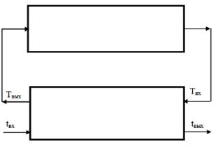
Fig. 1 shows a scheme of a cooler containing an isolated contour for cooling down an isolated premises. Note that both a direct-flow as well as the more effective counterflow scheme of indirect cooling can be employed.
|
|
|
|
|
|
|
Fig. 1. Scheme of a cooler containing an |
|
|
|
|
|
|
|
|
isolated contour for cooling |
|
|
|
|
|
|
|
an insulated premises |
||
Tinput |
||||||||
|
Toutput |
|
||||||
|
|
|
|
|
|
|
|
|
|
|
|
|
|
|
|
|
|
tinput |
|
|
|
toutput |
|
|
||
|
|
|
|
|
|
|
|
|
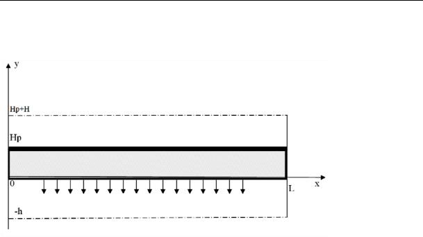
Ducts of an evaporating block during indirect cooling are divided into dry and wet ones (Fig. 2).
The temperature of the air passing through wet ducts where water evaporation occurs will be denoted as t. The temperature of the air passing through dry ducts and not changing its mois-
71
Russian Journal of Building Construction and Architecture
ture content will be denoted as T. The surface of the plates forming these ducts with the temperature Тр is waterproof (indicated with a dark line).
Axis of the section of a dry duct
Fig. 2. Fragment of an evaporating nozzle
Evaporation
Axis of the section of a wet duct
2. Material of the evaporating plates
The material of the surface of the plates forming wet ducts should have sufficient capillary properties and a free volume as well as open pores and water resistance. This problem has been addressed by a group of specialists run by V.M. Dubovoy who designed “a composite for special equipment” with this particular structure [1, 2]. Experimental studies showed that this material is good enough to be used for wet ducts of evaporating nozzles. The studies [3, 4] deal with modeling physical processes in indirect water evaporating coolers.
3. Modeling physical processes in indirect water evaporating coolers
Heat transfer in dry and wet ducts foracounterflowisdescribedbymeans of parabolicequations:
|
T |
|
|
|
|
|
|
|
T |
|
|
|
|
|
|
VT (x, y) C |
|
|
|
(T ) |
|
, |
|
x (0,L), |
y (Hp,Hp H ), |
||||||
x |
|
|
y |
|
|||||||||||
|
|
y |
|
|
|
|
|
|
|
||||||
Vt (x, y) C |
t |
|
|
|
|
|
(t) |
t |
|
, |
x (0,L), |
y ( h,0); |
|||
|
|
|
|
||||||||||||
x |
|
|
|
|
|||||||||||
|
|
|
|
|
y |
|
|
y |
|
|
|
||||
the mass exchange in the wet duct is as follows:
|
W |
|
|
|
W |
|
|
|
|
|
Vt (x, y) |
|
D(t) |
|
, |
x (0,L), |
y ( h,0). |
||||
x |
|
y |
||||||||
|
|
y |
|
|
|
|
||||
The temperature distribution law in the plate is given by the Laplace’s equation:
2Tp |
|
2Tp |
0, |
x (0,L), |
y 0,Hp . |
x2 |
|
y2 |
|
|
|
72
Issue № 4 (36), 2017 |
ISSN 2542-0526 |
The conditions at the input of the cooler for the counterflow takes the following form:
t |
|
x 0 |
tвх, x 0 |
вх, |
y ( h,0), |
||
|
|||||||
|
|
||||||
|
|
|
T |
|
x L Tвх, |
y (Hp,Hp H ). |
|
|
|
|
|
||||
|
|
|
|
|
|
||
Due to the symmetry at the axes of the ducts: |
|
|
|||||
T |
|
|
0, |
x (0,L), |
t |
|
|
|
0, |
x (0,L), |
W |
|
0, |
x (0,L). |
y |
|
|
y |
|
|
y |
||||||||
|
y Hp H |
|
|
|
y h |
|
|
|
y h |
|
||||
|
|
|
|
|
|
|
|
|||||||
At the ends of the plates let us specify the impermeability conditions:
Tp |
|
|
0, |
y (0,Hp), |
Tp |
|
0, |
y (0,Hp) |
|
|
|
||||||
x |
|
x 0 |
|
|
x |
|
x L |
|
|
|
|
|
|
At the boundary between the ducts and plate the equations of the temperatures and heat flows are specified:
T |
|
y Hp Tp |
|
y Hp , |
x (0,L), |
t |
|
y 0 |
Tp |
|
y 0 , |
x (0,L), |
||
|
|
|
|
|||||||||||
|
|
|
|
|
|
|||||||||
|
|
(T ) T |
пл(Tp) Tp , |
y Hp, |
|
x 0,L . |
||||||||
|
|
y |
|
y |
|
|
|
|
|
|
|
|
||
On the evaporation surface: |
|
|
|
|
|
|
|
|
|
|
||||
R(t)D W пл (Tp) Tp (t) |
t |
, y |
|
0, |
x (0,L). |
|||||||||
y |
|
|||||||||||||
|
|
y |
|
y |
|
|
|
|
|
|
|
|||
The diffusion coefficient, m2/seс, is assumed to be
D 10 5 2.16 1 t /273 1,8 .
And finally, the density of the vapor in the saturation line, kg/m3, is given by the formula:
wн t 0.0004212t3 0.001831t2 0.4195t 4.727 10 3 ,
obtained by means of approximation of the table data. Here W is the density of the vapor, kg/m3; λdensity, ρ, С is the heat conductivity of the plate, Watt/m/degrees, respectively, the density of the air, kg/m3, and specific heat capacity, J/kg/degrees; R(t) (2500.6 2.372t) 103 is a specific heat of vapor formation, J/kg; ε is an experimentally identified multiplier that accounts for extra energetic additive during evaporation from porous surfaces.
73

Russian Journal of Building Construction and Architecture
4. Implementation of a mathematical model
As this mathematical model includes elliptic and parabolic equations, the distribution of the temperatures should be searched for in the intergral block dividing the section of the plate as well as half of the section of the wet and dry ducts with a rectangular grid where groups of finite difference analogues that ate included in the above equation model are composed.
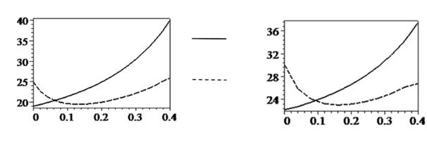
The obtained system of linear algebraic equations is solved for the values of the density of the saturated vapor and diffusion coefficient calculated at the temperature of the outside air. After that on the wet surface of the plate the density of the saturated vapor is corrected depending on the obtained temperatures. Besides, the diffusion coefficient in the nodes of the grid is also calculated using the specified temperature and then the system is solved again. The iteration process is over when the temperatures in the previous and current iteration at the output of the cooler are no less than 0.1 0С different. As an example, in Fig. 3 the solution of the specified system is visualized for the following parameters: the temperature at the input of the cold air is 25 0С, its relative humidity is 40 %, the temperature at the input of the hot air is 40 0С, the flow rate of the cold air is 2.7 m/seс, the flow rate of the hot air is 4 m/seс, the length of the plates is 0,4 m, the temperature at the output of the cold air is 25.8 0С, the temperature at the output of the hot air is 19 0С. Note that the temperature of the hot air at the input of the cooler Тinput is that at the output of the cooled down premises tpremises, which depends on the heat emissions in it. The heat balance equation in the premises is as follows:
C GTвых Q ki Fi tн tоб C Gtоб 0, |
(1) |
where ΣkiFi are the heat transfer coefficients and area of the i-th part of the walls of the cooled down premises; G is the consumption of the hot air; Тoutput is the temperature at the output of the cooler that is that at the input into the premises; tн is the temperature of the external environment that equals that at the input into the wet ducts; Q are thermal emissions in the premises.
Using the equation (1) the temperature in the premises is expressed:
|
C GT |
Q |
k Ft |
|
|
tоб |
вых |
|
i i н |
. |
(2) |
|
|
|
|||
|
ki Fi C G |
|
|||
Thus the temperature of the hot air at the input of the cooler depends of that of the hot air at the output of the cooler. This makes it necessary to arrange an external iteration cycle, which means the following. Some original temperature of the hot air at the input of the cooler is specified: Тinput = tpremises and the above model of heat and mass exchange in the cooler is im-
74
Issue № 4 (36), 2017 |
ISSN 2542-0526 |
plemented that is used to calculate the temperature at the output of the cooler is the temperature at the input of the premises. Furthermore, based on the equation (2) the temperature in the premises is determined and then the definition of misalignment as an absolute difference between the obtained and original values of tpremises is introduced. Then Тinput is corrected and the model of heat and mass exchange is implemented again. The calculations stop when the misalignment is less than 0.1 оС. Fig. 4 shows the distribution of the temperatures in the cooler of the same geometric size following the last iteration of the suggested algorithm for the following parameters: the outside temperature is 30 0С, the relative humidity is 40 %, the consumption of the dry air is 400 m3/h, %, the consumption of the wet air is 270 m3/h, heat emissions in the premises are 2000 Watt, the temperature in the premises is 37.5 0С. Note that if regular ventilation was used with the same consumption of the air, the temperature in the premise would reach 45.3 0С.
Temperature, degrees, C
Hot air
Cold air
Length, m
Temperature, degrees, C
Length, m
Fig. 3 |
Fig. 4 |
Conclusions
1.The results of the study allow one to conclude that the temperature in an isolated premises particularly of electronic equipment can be significantly reduced using cost-effective environmental- ly-friendlyindirect water evaporatingcoolers.
2.Additionally, the suggested mathematical model describing heat and mass transfer in the above coolers and method of its numerical implementation can be used for coolers that employ other cooling principles as well as for direct-flow and counterflow plate heat exchangers.
References
1. Dubovyy V. K. Bumagopodobnye kompozitsionnye materialy na osnove mineral'nykh volokon. Avtoref. diss. dokt. tekhn. nauk [Paper-like composite materials based on mineral fibers. Dr. eng. sci. diss.]. Saint Petersburg, 2006. 34 p.
75