Материал: Russian Journal of Building Construction and Architecture
Russian Journal of Building Construction and Architecture
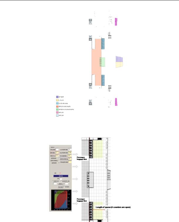
Fig. 25. Layout strategy plan 1 –– Check in area
Fig. 26. Layout strategy 1 of check-in area and ATArch-Analysis
When the ticket control space is solved as in Fig. 26, it will have designed its “own space”. When enough of space is saved for check-in activity area, the circulation of passengers will not be prevented. Provided that the number of check-in in ticket control area is kept constant, this can be analyzed as in Fig. 27.
26
Issue № 4 (36), 2017 |
ISSN 2542-0526 |
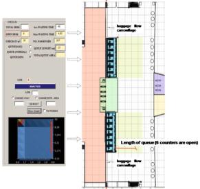
Fig. 27. Layout strategy 2 and ATArch-A analysis-Check-in area
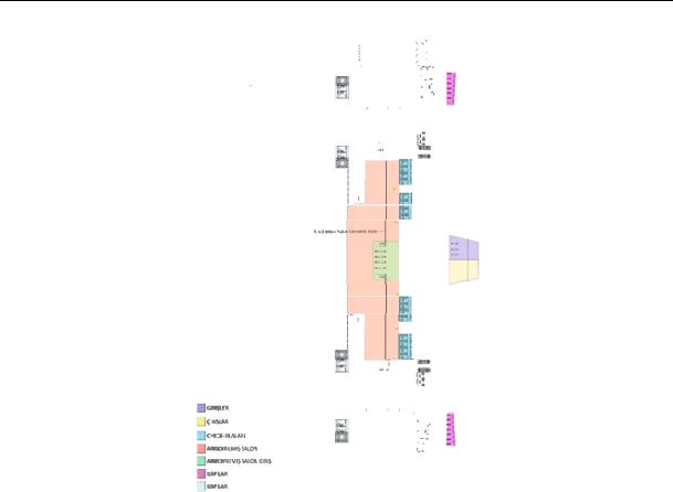
When the arrangement of check-in counters is done as in Fig. 27, it should cover the whole space and placed linearly (Fruin, 1971). IATA attributes the necessity of this linear placement to many factors, the most important one of which is the need to camouflage the luggage flow. That is why, such mistakes occur in some small terminals. On the other hand, undefined spaces form right along the luggage flow camouflage line, which the passengers cannot use. Regardless of whether they are linear type, pier type, or other concept, the situation of check-in counter desks is significant for passenger-flow. Accordingly, designers and some international institutions (FAA, 1983; ICAO, 1987; FAA, 1997; ICAO, 2004) have developed standard design forms. However, ATArch-A analyses show that where and how to design it is directly related with the number and characteristics of the passengers that are to use an airport. Among the check-in counters, the most different design method is the "island type" check-in counter. It is generally seen in large scale linear terminal buildings. Indeed, it is seen in centralized linear type terminals. If each check-in counter island is situated parallel to the direction of passengers’ flow through terminal entrance control hall, it means 10––20 separate check-in counters on each side. The desks on each side of the check-in island stand back to back, each having a luggage conveyor below. The suggested distance between two islands is 24––26 meters (IATA, 1995a). Also, there must be information boards and screens for ticketing processes in front of each check-in desk. Each check-in island is marked with a number or letter (IATA, 1995b). And sometimes, the area between two islands is numbered. The island type check-in counter space is shown in Fig. 28.
27
Russian Journal of Building Construction and Architecture
Fig. 28. Island type arrangement and analysis of ticket control space
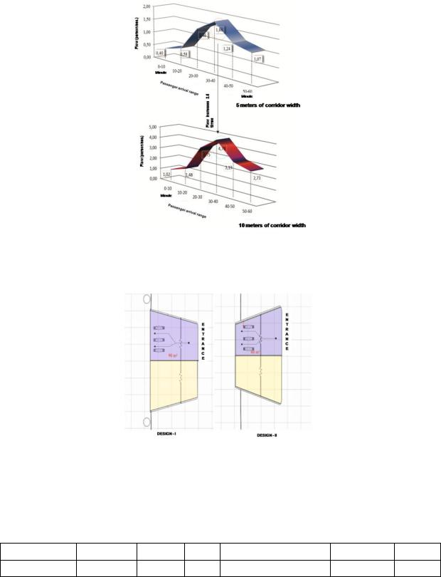
In this design, circulation area has to form behind the check-in counters in the island type ticket control space. The passengers are directed from this circulation space to departure hall. Fig. 29 displays the ATArch-A analysis. Here, the walking distance of the circulation area is taken as 5 meters, and the walking pace is taken as 0.71 m/sec. Circulation area was doubled, and passengers’ pace was taken as 0.91 m/sec. The average pace was taken as 0.71 m/sec in a 5-meter circulation space and as 0.91 m/sec in a 10 meter circulation space due to the average passenger pace found in observations of two corridors that are of similar type.
The flow analysis shows that the biggest disadvantage of island designs is that it leads to a problematic space behind the check-in place during group check-in. The passengers head from spacious places towards narrower places, which hinder the passenger flow. The entrance control hall was also analyzed in the same design concept. Figure 30 presents entrance control halls designed with two different concepts.
Design-1 is a design which becomes progressively wider from the terminal entrance towards x-ray area in the entrance control hall, whereas design-2 is one which becomes progressively narrower from the terminal entrance towards x-ray area. The square meters are set in these
28
Issue № 4 (36), 2017 |
ISSN 2542-0526 |
designs. All one has to do for a ATArch-A analysis is to upload the same number of passengers in both designs and enter the data set for spaces to ATArch-A. These data are displayed in Table 4.
Fig. 29. ATArch-A flow analysis of Island type check-in counters
Fig. 30. Entrance control halls designed with two different concepts
Table 4
Input variables for entrance control hall analysis
Ave.Wait |
PSÖY |
PSY |
B |
YK |
G-XRAY |
Gap |
27 |
303 |
321 |
N |
90E/95G/90N |
3/2 |
7 |
29
Russian Journal of Building Construction and Architecture
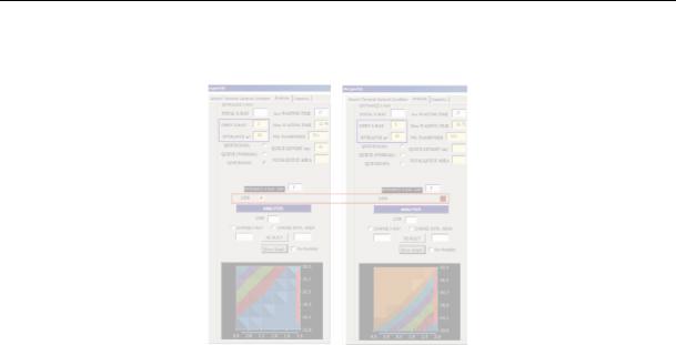
Fig. 31 presents the ATArch-A analysis.
Fig. 31. Analysis of entrance control halls designed with different concepts
ATArch-A analysis reveals that service level in design-1 is “A”, whereas it is “F” in design-2. This was mainly caused by the fact that one of the x-ray appliances in design-2 could not be used due to a design related reason. Because of this, although there are three x-ray appliances, only two of them are in use. X-ray appliances solved with columns (e.g., columns placed adjacent to column pillows, or those obstructed by something placed in front) are a few examples to such wrong applications. What is more, in design-1, the whole space area is 90 m². Here 30 m² is spared to the x-ray, with a remaining area of 60 m², which is left for possible formation of queues. However, in design-2, the whole area is 60 m². Here, 20 m² is spared for the x-ray, leaving 40 m² for possible queues. Because of this, it is crucial that the entrance control halls be solved by a rather flat geometry or by a concept that gets wider inwards for the smooth operating of entrance control hall. In addition, as soon as one x-ray appliance was activated, the service level in the space changes, which was shown by ATArch-A. Leaving from this, implementation of architecture that can expand or allows for potential expansion is crucial for smooth running of the terminal building. After examining architectural structures built with linear design concept, the "pier type" terminal was designed. Many presently used terminal designs were examined to establish a common ground for the pier type terminal design. The analysis screen shows that entrance control hall is insufficient and it is about to get congested. It further shows that departure hall entrance area is also congested, that the flow has completely stopped, and that the level of service is unacceptable. Moreover, the analysis
30