Материал: Russian Journal of Building Construction and Architecture

Russian Journal of Building Construction and Architecture
References
1.ACIE, Airports Council International Europe, 2003. ACI Traffic Forecasts: 2002––2020. Airports Council International, Geneva.
2.Brunetta L. and G. Romanin-Jacur. Passenger and baggage flow in an airport terminal: a flexible simulation model. Journal of Air Traffic Management, 1999, no. 6, pp. 361––363.
3.Correia A. R., Wirasinghe S. C. Evaluation of Level of Service at Airport Passenger Terminals: A Review of Research Approaches. Transportation Research Record 1888, National Research Council, Washington DC, 2004, pp. 1––6.
4.de Neufville R. and Odoni A. Airport Systems Planning, Design, and Management, McGraw-Hill, New York, NY. 2003.
5.Federal Aviation Administration FAA, Airport Capacity and Delay, 1983. AC Number:150/5060-5.
6.Federal Aviation Administration FAA. Federal Aviation Administration, ˝Aviation Noise Effect˝, Washington, DC, 1985, pp. 89––95.
7.Federal Aviation Administration FAA. INM technical manual version 5.1. Report No. FAA-AEE-97-04, Federal Aviation Administration, Washington, DC, 1997.
8.Fruin J. J. Pedestrian planning and design, 1971. 206 p.
9.Hsu C. I., & Chao C. C. Space allocation for commercial activities at international passenger terminals. Transportation Research Part E: Logistics and Transportation Review, 2005, no. 41 (1), pp. 29––51.
10.IATA, 2004. Airport Development Reference Manual, 9th ed. International Air Transport Association, Mon- treal-Geneva.
11.IATA, 1995a. Airport Development Reference Manual, 8th Edition.
12.IATA, 1995b. Airport Development Reference Manual, 8th ed. International Air Transport Association, Montreal-Geneva.
13.ICAO, 1987. Airport Planning Manual Doc 9184-AN/902. Part 1, Master Planning (2nd Ed).
14.ICAO, 2004. Annex 14 Aerodromes. Vol. 1. Aerodrome Design and Operation.
15.Pearce, B. (2015). Economic performance of the airline industry. Retrieved March, 1, 2016.
16.Teknomo, K. Modeling mobile traffic agents on network simulation. Transportation Science Society of the Phillippines, 2008.
17.TRBNRC, 2010. Transportation Research Board Airport Passenger Terminal Planninf and Design, ACRP Report 25.
36

Issue № 4 (36), 2017 |
ISSN 2542-0526 |
BASES AND FOUNDATIONS,UNDERGROUND STRUCTURES
UDC 624.15
Ya. A. Pronozin1, D. V. Rachkov2
THEORETICAL STUDIES OF THE FEATURES OF STRESS-STRAIN OF A FOUNDATION LOADED ALONG AN UPWARD-CONVEX CURVED SURFACE
Tyumen' Industrial University
Russia, Tyumen', tel.: (3452) 461-010, e-mail: Rachkov1991@yandex.ru 1D. Sc. in Engineering, Assoc. Prof. of the Dept. of Geotechnics
2PhD student of the Dept. of Geotechnics
Statement of the problem. The formation of VAT of a subgrade loaded along an upward-convex curved surface (e. g., shell) is sure to have a number of important features. The nature and a form of loading will have a great influence as well as the characteristics of the deformability of a foundation. In the case of a combination of certain factors there is a resulting increase in the hardness of a foundation when it is loaded along a curved contact surface. This effect has made it necessary to conduct a detailed study of the VAT base loaded along an upward-convex curved surface.
Results. A literature review of some cases of defining VAT of a semi-space with a complex relief is presented. Numerical simulation of loading of a soil foundation along a convex contact surface for different current characteristics of an acting load, boom and soil conditions. The dependences of the effects of the shape and type of loading on the final settling calculated taking into account formative and volumetric deformation were obtained. Options for settling of a foundation on a changing deformation modulus along the depth were examined. A positive effect (up to 53 %) of using loading along a curved up curved contact surfaces of a semi-plane was identified.
Conclusions. The results of the numerical simulation showed the efficiency of the use of foundations with an upward-convex curved contact surface. The increase in the stiffness of a soil foundation is due to an additional lateral compression of the soil owing to the characteristics of the shape of a contact surface.
Keywords: basis, foundation, semi-space with a complex relief, curved surface, modeling, deformation.
Introduction
It is obvious that loading of the base in suspension parts of band-shell foundation under the shells along a curved surface might contribute to the stress-strain of the base. A change in the
© Pronozin Ya. А., Rachkov D. V., 2017
37

Russian Journal of Building Construction and Architecture
strain field in relation to loading along a flat surface might cause changes of the ratios of the stress tensor component at the base points and thus lead to extreme stress-strain and deformation of the base.
1. General assumptions
For boundary surfaces, e.g., wedges, parabolas, semicircular hollows, for a linear model of the foundation a flat task is reduced to a joint solution of the equations of balance [4]:
x |
xy |
X , |
y |
|
xy |
Y ; |
(1) |
x |
y |
|
y |
x |
|
|
|
of compatibility: |
|
|
|
|
|
|
|
x y |
|
|
1 |
|
|
X |
|
Y |
|
; |
(2) |
|
|
|
|
|
|||||||
1 |
|
|
x |
y |
|||||||
|
|
|
|
|
|
||||||
for the boundary conditions: |
|
|
|
|
|
|
|
|
|
|
|
pxv x l xy m; |
|
|
|
pyv x m xy l, |
(3) |
||||||
where l, m are direction cosines on the boundary curve; pxν, pyν are the components of the boundary strains.
This is a formulation of the first main task of the elasticity theory solved in strains that is true for linear-deformed foundation massivees that are in a stabilized condition. It is proven in the elasticity theory that if volumetric forces are constant in a certain area, instead of three functions (a flat task) σх, σу, τху one function of strains φ(х, у) –– the Airy function (1862) –– can be identified that satisfies the balance equation (1) and a biharmonic equation:
4 |
2 |
4 |
|
4 |
0. |
(4) |
||
x4 |
x2 |
y2 |
y4 |
|||||
|
|
|
|
|||||
The components of the stress tensor are determined using the partial derivatives of φ(х, у):
x |
2 |
*x , |
y |
2 |
*y , |
xy |
2 |
*xy , |
(5) |
y2 |
x2 |
x y |
where *x , *y , *xy are any partial solutions that satisfy (1). The ways of identifying the Airy
function depend on the shape of a massiveive relief and are a complex mathematical task that is solved using conformal mapping.
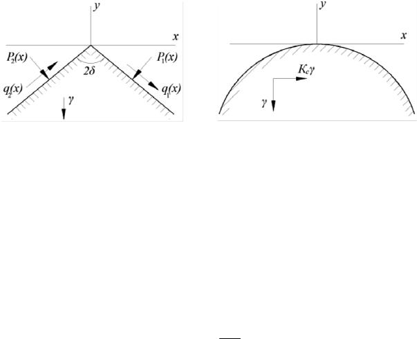
The task involving the wedge (Fig. 1а) is presented by А. Lyav (1935) [6] and B. G. Galerkin (1952) [3] for when there are normal and tangential forces on the surface that change according to the straight line law.
The task involving the parabolic relief (Fig. 1b) has been dealt with by Z. G. Ter-Martirosyan, D. M. Akhapatelov, R. G. Manvelyan (1974) for gravitation and seismic forces [14].
38
Issue № 4 (36), 2017 |
ISSN 2542-0526 |
G. V. Коlosov and N. I. Muskhelishvili developed a method of complex potentials that allows the solution of the flat task of the elasticity theory to be obtained using the Airy stress functions if it is presented as a combination of two functions of a complex variable called complex potentials [7].
Note that all the above solutions are based on the classical elasticity theory.
In this chapter in order to determine the stress-strain of the foundation loaded along a curved surface, the finite element method is used that is also based on the resolving equations of the elasticity theory. The study of the base foundation takes place in a range of extra pressure that does not exceed the design resistance of the foundation specified by SP 22.133300.2011. The accuracy of the solution in the finite element method is determined by the sizes of the grid of dividing an elastic half-space and if certain conditions are satisfied in the range of minimum errors, it corresponds with accurate analytical solutions.
а) |
b) |
Fig. 1. Calculation schemes for the tasks involving the wedge (а), parabolic relief (b)
A geotechnical analysis software PLAXIS 2D AE is employed to implement the finite element method.
The task of the study was to determine the stress-strain of the foundation loaded along the upward curved surface corresponding to the contact surface of the suspension parts of the band-shell foundation under the shells.
A special prominence is given to determining the lateral pressure σx that directly impacts the way the stress-strain of the foundation massiveive is determined. σx is assumed according to the geostatics principles unless there are reliable OCR data, i.e.
|
|
x z 1 . |
(6) |
The value of σxp can be obtained using the solutions of the elastic half-space theory. However, it is to be remembered that in the classical interpretation of the Poisson coefficient v = 0.5 for
39
Russian Journal of Building Construction and Architecture
an elastic half-space can be considerably different from the value of actual foundations. Based on general logic, for loaded foundations it is reasonable to consider determining σxp using the above dependence that is employed in the PLAXIS software.
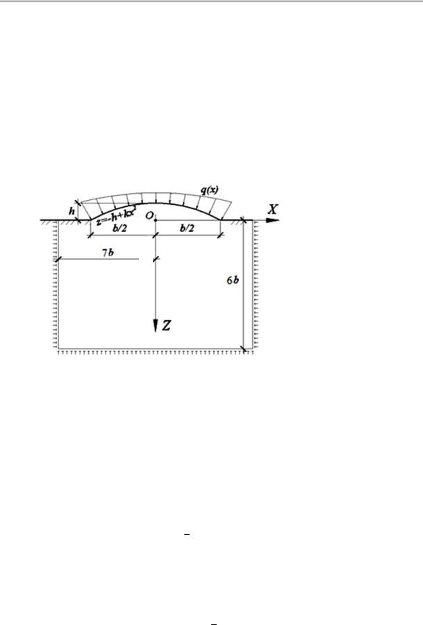
A load is assumed to be flexible, which is in correspondence with the solutions employed in SP [13] and the construction features of a thin-walled shell. A load which is symmetrical to the axis Z and acts along the normal to the surfaces is assumed to be equivalent to loading along a flat surface, i.e. a projection of a considered load onto the vertical axis in the range of the loading width is constant (Fig. 2).
Symmetry axis
Fig. 2. Calculation scheme
A flat task. A load onto a bulging curved surface is band and eternal in the direction perpendicular to the plane XOZ. A cylindrical curved surface is described using the function of the quadratic parabola. Choice of the function is based on the preliminary calculations and literature review. The boundaries of the investigated area range from 7b to 7b along the axis Х and 6b along the axis Z, where b is the width of the loading that equals that of the conditional band-shell foundation. The foundationbase is in accordancewith the criteriaof the linear deformed medium.
2. Effect of the character of loading of the surface on the deformity of a foundation base
A loading of a foundation base with a flexible load along a flat and curved surface is examined. The loading schemes are in Fig. 3: h 0.2, b = 2.4 m, p = 95 kPa, q = 30 kPa, ν = 0.499, Нсж = 3.0 m, Е = 10 МPа. While calculating heaving zp , *zp , x are assumed to be along the foundation axis where σzp are extra vertical compressive stresses assumed to be the same as for a foundation with a flat contact surface; *zp are extra vertical compressive stresses assumed to be accordingtoacalculationin PLAXIS 2D AE; h h /b is a relative rising height of a surface.
40