Материал: m083300e
82 • Fieldbus coupler / controller
Fieldbus Controller 750-833
3.2.2.7Operating mode switch
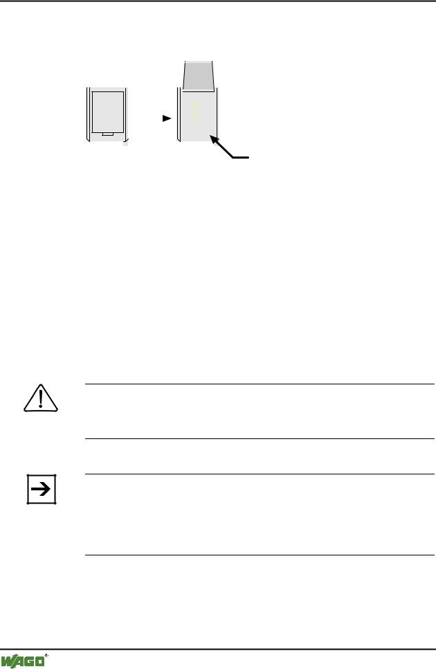
The operating mode switch is located behind the cover flap.
|
|
|
|
|
|
|
|
|
|
|
Betriebsartenschalter |
|
|
|
|
|
|
|
|
|
|
|
|
|
|
|
|
|
|
|
|
|
|
|
|
|
|
|
|
|
|
|
|
|
|
|
|
|
|
|
|
|
|
|
|
|
|
|
|
|
|
|
|
|
|
|
|
|
|
|
|
|
|
|
|
|
|
|
|
|
|
|
|
|
|
|
|
|
|
|
|
|
|
|
|
|
|
|
|
|
|
|
|
|
|
|
|
|
|
|
|
|
|
|
|
|
|
|
|
|
|
|
|
|
|
|
|
|
|
|
|
Fig. 3-18: Operating mode switch |
|
g01xx10d |
|||||||||
The switch is a push/slide switch with 3 settings and a hold-to-run function.
Operating mode switch |
Function |
From middle to top position |
Activate program processing (RUN) |
|
|
From top to middle position |
Stop program processing (STOP) |
|
|
(Lower position, bootstrap) |
(For original loading of firmware, |
|
not necessary for user) |
|
|
Push down |
Hardware reset |
(e.g with a screwdriver) |
All outputs and flags are reset; variables are set to 0 or to |
|
FALSE or to an initial value. |
|
The hardware reset can be performed with STOP as well |
|
as RUN in any position of the operating mode switch! |
|
|
Attention
If outputs are set when switching over the operating mode switch from RUN to STOP they remain set! Switching off on the software side e.g. by initiators, are ineffective, because the program is no longer processed.
(An operating mode is internally changed at the end of a PLC cycle.)
Note
With "GET_STOP_VALUE" (library "System.lib") WAGO-I/O-PRO 32 provides a function which serves to recognise the last cycle prior to a program stop giving the user the possibility to program the behaviour of the controller in case of a STOP. With the aid of this function the controller outputs can be switched to a safe condition.
D R A F T |
WAGO-I/O-SYSTEM 750 |
2001-02-27 |
PROFIBUS |

Fieldbus coupler / controller |
• 83 |
Fieldbus Controller 750-833 |
|
|
|
3.2.3Operating system
3.2.3.1Run-up
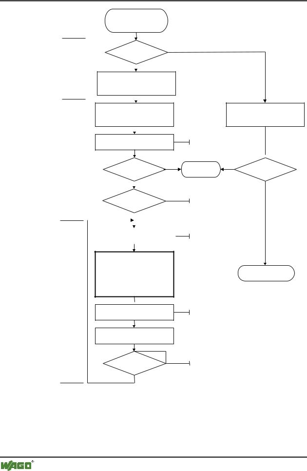
The controller runs-up after switching on the supply voltage or after a hardware reset. The PLC program in the flash memory is transferred to the RAM. The "I/O" LED flashes orange.
The controller then checks all functions of its modules in a self test, the internal bus and the fieldbus interface. Following this the I/O modules and the present configuration is determined. At the same time a list is generated which is not visible from outside. This includes an input and an output area, which shows on the fieldbus RAM of the fieldbus RAM. This is followed by the initialisation of the system. The variables are set to 0 or to FALSE or to an initialisation value given by the PLC program. The flags retain their status . The "I/O" LED blinks red during this phase.
Following a fault free run-up the controller changes over to the "Fieldbus start" mode. The "I/O" LED lights up green.
A PLC program does not yet exist in the flash memory when delivered. The controller runs-up as described, without initialising the system. It then behaves as a coupler.
3.2.3.2PLC cycle
The PLC cycle starts following a fault free run-up when the operating mode switch is in the top position or by a start command from the WAGO-I/O-PRO 32. The input and output data of the fieldbus and the I/O modules as well as the times are read. Subsequently the PLC program in the RAM is processed followed by the output data of the fieldbus and the I/O modules in the process image. Operating system functions, amongst others, for diagnosis and communication are performed an the times actualised at the end of the PLC cycle. The cycle starts again with the reading in of the input and output data and the times.
The change of the operating mode (STOP/RUN) is made at the end of a PLC cycle.
The cycle time is the time from the start of the PLC program to the next start. If a loop is programmed within a PLC program the PLC running time and thus the PLC cycle are extended correspondingly.
The inputs, outputs and times are not updated during the processing of the PLC program. This actualisation occurs in a defined manner only at the end of the PLC program. For this reason it is not possible to wait for an event from the process or the elapse of a time within a loop.
WAGO-I/O-SYSTEM 750 |
D R A F T |
PROFIBUS |
2001-02-27 |
84 • Fieldbus coupler / controller
Fieldbus Controller 750-833
Versorgungsspannung
einschalten oder
Hardware-Reset
|
|
SPS-Programm |
|
Nein |
|||||
|
|
im Flash-Speicher |
|
|
|
||||
“I/O”-LED |
|
|
|
Ja |
|
|
|
||
|
|
|
|
|
|
||||
blinkt |
|
|
|
|
|
|
|||
|
|
|
|
|
|
||||
|
|
|
|
|
|
|
|||
orange |
SPS-Programm |
|
|
|
|||||
|
|
vom Flash-Speicher |
|
|
|
||||
|
|
ins RAM übertragen |
|
|
|
||||
|
|
|
|
|
|
|
|||
|
|
|
|
|
|
|
|
||
|
|
Controller-Selbsttest, |
|
|
|
||||
|
|
Ermittlung Busklemmen |
|
|
|
||||
|
|
und Konfiguration, |
|
|
|
||||
|
|
Erstellung interner Liste |
|
|
|
||||
“I/O”-LED |
|
|
|
|
|
|
|
||
|
|
|
|
|
|
|
|||
|
|
|
|
|
|
|
|||
blinkt |
Initialisierung des Systems |
||||||||
rot |
|||||||||
|
|
|
|
|
|
|
|||
|
|
Fehler |
Ja |
||||||
|
|
|
|
|
|||||
|
|
|
|
|
Nein |
|
STOP |
||
|
|
|
|
|
|
||||
|
|
|
|
|
|||||
|
|
Betriebsart |
|
||||||
|
|
|
|
|
|||||
|
|
|
|
|
RUN |
|
|
|
|
|
|
|
|
|
|
|
|
||
SPS- |
|
|
|
|
|
|
|
||
|
|
|
|
|
|
|
|||
Ein-/Ausgänge u. Zeiten lesen |
|
||||||||
Zyklus |
|
||||||||
|
|
|
|
|
|
|
|||
|
|
|
|
|
|
|
|
|
|
Im RAM vorhandenes SPS-Programm bearbeiten
“I/O”-LED
grün an  Ausgänge schreiben
Betriebssystem-Funktionen,
Zeiten aktualisieren
STOP
Betriebsart
RUN
Fig. 3-19: Controller operating system
Controller-Selbsttest,
Ermittlung Busklemmen
und Konfiguration,
Erstellung interner Liste
Variablen auf 0 bzw. FALSE oder auf Initialwert setzen, Merker behalten ihren Zustand bei 
STOP |
Ja |
Fehler |
|
|
Nein |
Betriebsartenschalter: oberer Stellung oder WAGO-I/O-PRO 32: ‘Online’ ‘Start’/’Stop’
Feldbusdaten,
Busklemmendaten
Feldbusstart
Betrieb als Koppler
Feldbusdaten,
Busklemmendaten
Betriebsartenschalter: Stellungswechsel WAGO-I/O-PRO 32: ‘Online’ ‘Start’/’Stop’
g012112d
D R A F T |
WAGO-I/O-SYSTEM 750 |
2001-02-27 |
PROFIBUS |
Fieldbus coupler / controller |
• 85 |
Fieldbus Controller 750-833 |
|
|
|
3.2.4Process image
3.2.4.1Local process image
After switching on the controller recognises all I/O modules connected in the node, which are waiting for or transmitting data (data width/bit width > 0). In nodes analog and digital I/O modules can be fitted mixed.
Note
For the number of input and output bits or bytes of the individual switched on I/O modules please refer to the corresponding description of the I/O modules.
The controller generates an internal local process image from the data width and the type of I/O module as well as the position of the I/O modules in the node. This is divided into an input and an output area.
The data of the digital I/O modules are bit orientated, i.e. the data exchange is made bit by bit. The analog I/O modules are representative for all I/O modules which are byte orientated, in which the data exchange is also made byte by byte. These I/O modules also include, for example, counter modules, I/O modules for angle and path measurement as well as communication modules.
The data of the I/O modules is separated for the local input and output process image in the sequence of their position after the controller in the individual process image.
Note
If a node is changed or extended this may result in a new process image structure. In this case the process data addresses also change in comparison with earlier versions.
WAGO-I/O-SYSTEM 750 |
D R A F T |
PROFIBUS |
2001-02-27 |
86 • Fieldbus coupler / controller
Fieldbus Controller 750-833
3.2.4.2Allocation of the input and output data
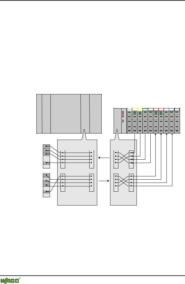
The process data is exchanged via the PROFIBUS with the higher ranking controls (Master). A maximum of 128 byte of data is transmitted from the master to the controller, or node to the output data. The controller returns a maximum of 128 byte input data as a reply to the master.
The modules are configured when projecting the nodes. These modules can be copied from a hardware catalogue by the configurations programs. The information covering the possible modules is saved in the GSD files.
The controller generates an internal mapping in accordance with the installed and configured settings of the node, in which the allocation of the input and output data is determined in the local process image with the position in the PROFIBUS DP Telegram.
Master, z. B. SPS
CPU
Anschaltung |
750- |
1 |
2 |
3 |
4 |
5 |
6 |
7 |
8 |
9 |
|
||||||||||
|
|
DI |
DI |
AI |
AI |
DO DO |
AO AO |
|
||
|
|
402 |
402 |
452 |
452 |
504 |
504 |
550 |
550 |
600 |
Master- |
|
|
|
|
Adressen |
|
|
|
|
I |
|
Zuordnungsliste |
Zuordnungsliste |
|
|
|
|||
|
I |
I |
I |
I |
|
|
|
PROFIBUS |
|
O |
O |
O |
O |
O |
|
|
|
PROFIBUS |
|
bitund byteweise byteweise Zuordnung, Zuordnung, Erstellung auf dem PC
Erstellung automatisch durch den Koppler
Fig. 3-20: Allocation of the input and output data |
g012117d |
D R A F T |
WAGO-I/O-SYSTEM 750 |
2001-02-27 |
PROFIBUS |