Материал: m083300e
92 • Fieldbus coupler / controller
Fieldbus Controller 750-833
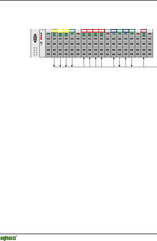
3.2.5.3Example
A fieldbus node with a controller and 17 I/O modules should make the arrangement clear.
1 |
2 |
3 |
4 |
5 |
6 |
7 |
8 |
9 |
10 |
11 |
12 |
13 |
14 |
15 |
16 |
17 |
DI DI |
DI DI |
DI DI |
AI AI |
DO DO DO DO DO DO DO DO |
AO AO |
AI AI |
AO AO AI AI |
DO DO |
750-333
402 |
402 |
402 |
452 |
602 |
504 |
504 |
504 |
504 |
602 |
550 |
452 |
550 |
452 |
602 |
504 |
600 |
Fig. 3-21: Example application
PROFIBUS
g012115x
No. |
I/O modules |
Modul |
PI Master * |
|
|
|
Identification |
|
|
|
|
Inputs |
Outputs |
|
|
|
|
||
1 |
Digital input |
750-402 4 DI/24 V DC/3.0 ms |
EB12.0 |
|
|
|
|
|
|
|
Digital input |
0x10 |
EB12.1 |
|
|
|
|
|
|
|
Digital input |
|
EB12.2 |
|
|
|
|
|
|
|
Digital input |
|
EB12.3 |
|
|
|
|
|
|
2 |
Digital input |
*750-402 4 DI/24 V DC/3.0 ms |
EB12.4 |
|
|
|
|
|
|
|
Digital input |
0x00 |
EB12.5 |
|
|
|
|
|
|
|
Digital input |
|
EB12.6 |
|
|
|
|
|
|
|
Digital input |
|
EB12.7 |
|
|
|
|
|
|
3 |
Digital input |
750-402 4 DI/24 V DC/3.0 ms |
EB13.0 |
|
|
|
|
|
|
|
Digital input |
0x10 |
EB13.1 |
|
|
|
|
|
|
|
Digital input |
|
EB13.2 |
|
|
|
|
|
|
|
Digital input |
|
EB13.3 |
|
|
|
|
|
|
4 |
Analog input |
750-452 2 AI/0-20 mA/diff. |
EW0 |
|
|
|
|
|
|
|
Analog input |
0x51 |
EW2 |
|
|
|
|
|
|
5 |
Potential supply |
Potential supply |
--- |
--- |
|
|
|
|
|
6 |
Digital output |
750-504 4 DO/24 V DC/0.5 A |
|
AB8.0 |
|
|
|
|
|
|
Digital output |
0x20 |
|
AB8.1 |
|
|
|
|
|
|
Digital output |
|
|
AB8.2 |
|
|
|
|
|
|
Digital output |
|
|
AB8.3 |
|
|
|
|
|
7 |
Digital output |
*750-504 4 DO/24 V DC/0.5 A |
|
AB8.4 |
|
|
|
|
|
|
Digital output |
0x00 |
|
AB8.5 |
|
|
|
|
|
|
Digital output |
|
|
AB8.6 |
|
|
|
|
|
|
Digital output |
|
|
AB8.7 |
|
|
|
|
|
D R A F T |
WAGO-I/O-SYSTEM 750 |
2001-02-27 |
PROFIBUS |

|
|
|
Fieldbus coupler / controller |
• 93 |
||||
|
|
|
Fieldbus Controller 750-833 |
|
|
|
||
|
|
|
|
|
|
|
|
|
|
|
|
|
|
|
|
|
|
|
8 |
Digital output |
750-504 4 DO/24 V DC/0.5 A |
|
AB9.0 |
|
|
|
|
|
|
|
|
|
|
|
|
|
|
Digital output |
0x20 |
|
AB9.1 |
|
|
|
|
|
|
|
|
|
|
|
|
|
|
Digital output |
|
|
AB9.2 |
|
|
|
|
|
|
|
|
|
|
|
|
|
|
Digital output |
|
|
AB9.3 |
|
|
|
|
|
|
|
|
|
|
|
|
|
9 |
Digital output |
*750-504 4 DO/24 V DC/0.5 A |
|
AB9.4 |
|
|
|
|
|
|
|
|
|
|
|
|
|
|
Digital output |
0x00 |
|
AB9.5 |
|
|
|
|
|
|
|
|
|
|
|
|
|
|
Digital output |
|
|
AB9.6 |
|
|
|
|
|
|
|
|
|
|
|
|
|
|
Digital output |
|
|
AB9.7 |
|
|
|
|
|
|
|
|
|
|
|
|
|
10 |
Potential supply |
Potential supply |
--- |
--- |
|
|
|
|
|
|
|
|
|
|
|
|
|
11 |
Analog output |
750-550 2 AO/0-10 V |
|
AW0 |
|
|
|
|
|
|
|
|
|
|
|
|
|
|
Analog output |
0x61 |
|
AW2 |
|
|
|
|
|
|
|
|
|
|
|
|
|
12 |
Analog input |
750-452 2 AI/0-20 mA/diff. |
EW4 |
|
|
|
|
|
|
|
|
|
|
|
|
|
|
|
Analog input |
0x51 |
EW6 |
|
|
|
|
|
|
|
|
|
|
|
|
|
|
13 |
Analog output |
750-550 2 AO/0-10 V |
|
AW4 |
|
|
|
|
|
|
|
|
|
|
|
|
|
|
Analog output |
0x61 |
|
AW6 |
|
|
|
|
|
|
|
|
|
|
|
|
|
14 |
Analog input |
750-452 2 AI/0-20 mA/diff. |
EW8 |
|
|
|
|
|
|
|
|
|
|
|
|
|
|
|
Analog input |
0x51 |
EW10 |
|
|
|
|
|
|
|
|
|
|
|
|
|
|
15 |
Potential supply |
Potential supply |
--- |
--- |
|
|
|
|
|
|
|
|
|
|
|
|
|
16 |
Digital output |
750-504 4 DO/24 V DC/0.5 A |
|
AB10.0 |
|
|
|
|
|
|
|
|
|
|
|
|
|
|
Digital output |
0x20 |
|
AB10.1 |
|
|
|
|
|
|
|
|
|
|
|
|
|
|
Digital output |
|
|
AB10.2 |
|
|
|
|
|
|
|
|
|
|
|
|
|
|
Digital output |
|
|
AB10.3 |
|
|
|
|
|
|
|
|
|
|
|
|
|
17 |
End module |
End module |
--- |
--- |
|
|
|
* The master addresses listed in the table correspond to the allocation of the process data given in the master configuration.
WAGO-I/O-SYSTEM 750 |
D R A F T |
PROFIBUS |
2001-02-27 |

94 • Fieldbus coupler / controller
Fieldbus Controller 750-833
3.2.6Parameterisation of the controllers
Before a data exchange can be performed between master and slave, a parameterisation is required in addition to configuration.
The extended parameters (Extended User_Prm_Data) are provided via the GSD files as selectable text in the configuration programs.
Description |
Value |
Meaning |
Restart the internal bus after a |
|
Restart of the terminal bus following a fault, |
fault |
POWER ON RESET*) |
such as, for example, no termination module |
|
following an interruption of the supply |
|
|
AUTORESET |
immediately after overcoming the internal bus |
|
|
fault |
I/O module diagnosis |
|
The diagnosis information of all I/O modules |
|
|
with a diagnosis capability, for which the |
|
released*) |
diagnosis is released are |
|
transferred to PROFIBUS-DP master, |
|
|
locked |
not transferred to PROFIBUS-DP master |
Process value display |
|
Word or double word oriented process data, is |
|
|
transferred to PROFIBUS-DP master in: |
|
INTEL |
„Little Endian Format“ |
|
MOTOROLA*) |
„Big Endian Format“ |
Behaviour in case of a |
|
In the case of a malfunction of the |
PROFIBUS DP fault |
|
PROFIBUS DP communication the status of the |
|
|
connected output periphery can be influenced in |
|
|
various ways: |
|
Stop internal bus transmis- |
The process data exchange on the internal bus is |
|
sion |
stopped, all outputs drop out after a module |
|
|
specific monitoring time of 100 ms |
|
Set output image to zero |
all outputs are immediately reset |
|
Freeze output image |
all outputs maintain the last status before the |
|
Write substitute value*) |
malfunction |
|
all outputs switch a parameterisable substitute |
|
|
|
value |
|
PFC fault strategy |
PFC takes over the control via the output image |
|
|
|
Reaction to an internal bus fault |
|
In the event of a malfunction of an internal |
|
|
communication between fieldbus controller and |
|
|
I/O modules, such as, for example no termina- |
|
|
tion module, |
|
Stop PROFIBUS data |
the data exchange with the PROFIBUS master |
|
exchange*) |
is stopped. |
|
Set input image to zero |
the input information is set to zero |
|
Freeze input image |
the input information prevailing before the fault |
|
|
is maintained |
|
*) Default settings |
|
D R A F T |
WAGO-I/O-SYSTEM 750 |
2001-02-27 |
PROFIBUS |

Fieldbus coupler / controller |
• 95 |
Fieldbus Controller 750-833 |
|
|
|
The complete data block encompasses 34 parameterised bytes. The first 10 bytes are laid down via the DP and DPV1 standard. The others receive manufacturer specific parameters.
Byte No. |
Bit No. |
Value |
Meaning |
|
Standard parameters |
|
|
|
|
0 |
0-7 |
|
Station status (see EN 50170) |
|
1 |
0-7 |
2-255 |
Watchdog factor 1 |
|
2 |
0-7 |
2-255 |
Watchdog factor 2 |
|
|
|
|
Watchdog: |
|
|
|
|
The response monitoring is the result of |
|
|
|
|
Watchdog_Factor_1 x Watchdog_Factor_2 x 10 ms (1 ms) |
|
3 |
0-7 |
11-255 |
Min TSDR, |
|
|
|
|
Earliest time in TBit after which the slave can reply |
|
4 |
0-7 |
183, 0xB7 |
Manufacturer Identification |
(high byte) |
5 |
0-7 |
86, 0x56 |
Manufacturer Identification |
(low byte) |
6 |
0-7 |
|
Group membership, |
|
|
|
|
Broad and multicast telegrams (SYNC, FREEZE) |
|
7 |
0-7 |
|
DPV1 status 1 (see EN 50170) |
|
8 |
0-7 |
|
DPV1 status 2 (see EN 50170) |
|
9 |
0-7 |
|
DPV1 status 3 (see EN 50170) |
|
Manufacturer parameters |
|
|
||
10 |
0-7 |
0 |
Table 0, register 0 LB, reserved |
|
11 |
0-7 |
0 |
Table 0, register 0 HB, reserved |
|
12 |
0-7 |
0 |
Table 0, register 1 LB, reserved |
|
13 |
0-7 |
0 |
Table 0, register 1 HB, reserved |
|
14 |
|
|
Table 0, register 2 LB |
|
|
0 |
0 |
Device diagnosis locked |
|
|
0 |
1*) |
Device diagnosis released |
|
|
1 |
0 |
Internal bus restart after fault: POWER-ON-RESET |
|
|
1 |
1*) |
Internal bus restart after fault: AUTORESET |
|
|
2-7 |
0 |
reserved |
|
15 |
0-7 |
0 |
Table 0, register 2 HB, reserved |
|
16 |
|
|
Table 0, register 3 LB |
|
|
0-2 |
'011' |
reserved |
|
|
3 |
0 |
Data format byte orientated I/O modules: INTEL |
|
|
3 |
1*) |
Data format byte orientated I/O modules: MOTOROLA |
|
|
4-7 |
'1100' |
reserved |
|
17 |
|
|
Table 0, register 3 HB |
|
|
0-2 |
'000' |
Reaction to fieldbus fault: |
|
|
|
- Stop internal bus transmission |
||
|
|
'001' |
- Set output image to zero |
|
|
|
'010' |
- Freeze output image |
|
|
|
'011' *) |
- Write substitute values |
|
|
|
'100' |
- PFC fault strategy |
|
|
|
'101' |
- Not possible |
|
|
|
'110' |
- Not possible |
|
|
|
'111' |
- Not possible |
|
|
3-5 |
'000' *) |
Reaction to internal bus fault: |
|
|
|
- Exit data exchange |
|
|
|
|
'001' |
- Set input image to zero |
|
|
|
'010' |
- Freeze input image |
|
|
|
'011' |
- Not possible |
|
|
|
'100' |
- Not possible |
|
|
|
'101' |
- Not possible |
|
|
|
'110' |
- Not possible |
|
|
|
'111' |
- Not possible |
|
|
6-7 |
'00' |
reserved |
|
18 |
0-7 |
'1100.0011' |
Table 0, register 4 LB, reserved |
|
19 |
0-7 |
'0111.1111' |
Table 0, register 4 HB, reserved |
|
20 |
0-7 |
'0000.0000' |
Table 100, register 0 LB, reserved |
|
21 |
0-7 |
'0000.0001' |
Table 100, register 0 HB, reserved |
|
22 |
0-7 |
'0000.0000' |
Table 100, register 1 LB, reserved |
|
23 |
0-7 |
'0000.0000' |
Table 100, register 1 HB, reserved |
|
24 |
0-7 |
'0000.0000' |
Table 100, register 2 LB, reserved |
|
25 |
0-7 |
'0000.0000' |
Table 100, register 2 HB, reserved |
|
WAGO-I/O-SYSTEM 750 |
D R A F T |
PROFIBUS |
2001-02-27 |

96 • Fieldbus coupler / controller
Fieldbus Controller 750-833
3.2.7Configuration of the process data channels
The process data channels serve the communication between the WAGO-I/O- PRO and the running time system of the fieldbus controller. If this channel is not required it can be projected with a process data length of zero
(750-833 No process data channel).
Module |
Identification |
Identification |
|
hex |
dec |
750-833 no process data channel |
0x00 |
0 |
750-833 2 byte process data channel |
0xB1 |
177 |
Note
Configure the module 750-833 2 byte process data channel or 750-833 No process data channel as 1st module.
D R A F T |
WAGO-I/O-SYSTEM 750 |
2001-02-27 |
PROFIBUS |