Материал: part17

Внимание! Если размещение файла нарушает Ваши авторские права, то обязательно сообщите нам

Page 636​

DICOM PS3.17 2020a - Explanatory Information​

Figure NNN.3-5. Corneal Topography Height Map Example​

NNN.4 Contact Lens Fitting Examples​

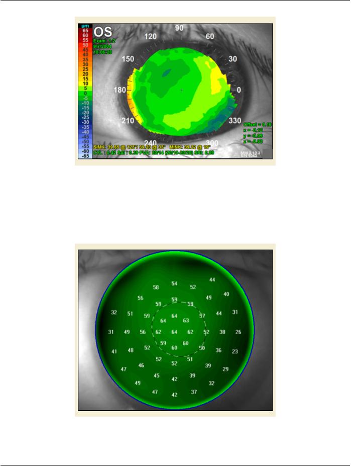
Knowledge of the anterior corneal shape is helpful in the fitting of contact lenses particularly in corneas that are misshapen by trauma,​ surgery, or disease. A contact lens base curve inventory or user design criteria are provided and these are used to evaluate contact​ lens fit and wear tolerance using a simulated clinical fluorescein test, shown in Figure NNN.4-1. The fluorescein pattern shows the​ contact lens clearance over the cornea. Numbers indicate local clearance in micrometers.​

Figure NNN.4-1. Contact Lens Fitting Simulation Example​

- Standard -​

DICOM PS3.17 2020a - Explanatory Information​

Page 637​

NNN.5 Wavefront Map Example​

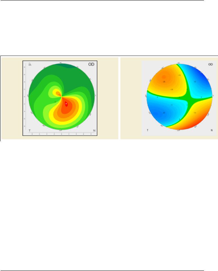
Ocularwavefrontproducesameasurementofopticalpathdifference(OPD)betweenidealopticalsystemandtheonebeingmeasured.​ Typically the OPD is measured and displayed in units of microns. Wavefront maps can be produced from the corneal surfaces, most​ often the front surface, since this is the major refracting surface in the eye account for about 80% of the ocular power.​

Wavefront maps can be calculated directly from corneal elevation data most often using the Zernike polynomial fitting series. With​ this method, corneal optical characteristics such as astigmatism, spherical aberration, and coma can be calculated. Generally, the​ lower order (LO) aberrations (offsets, refractive error and prism) are eliminated from display, so that only the higher order (HO) aber-​ rations remain, shown in Figure NNN.5-1.​

Numbers indicate deviations from a perfect optical element.​

Figure NNN.5-1. Corneal Axial Topography Map of keratoconus (left) with its Wavefront Map showing​ higher order (HO) aberrations (right)​

- Standard -​

Page 638​

DICOM PS3.17 2020a - Explanatory Information​

- Standard -​

DICOM PS3.17 2020a - Explanatory Information​

Page 639​

OOO Radiopharmaceutical Radiation Dose​

Structured Report (Informative)​

OOO.1 Purpose of This Annex​

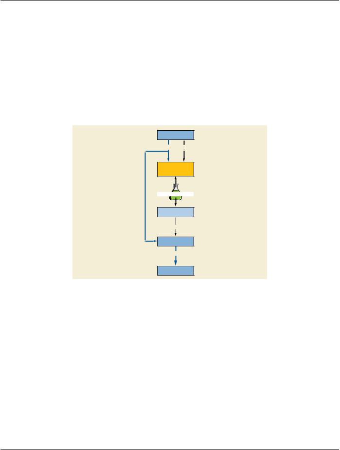
ThisAnnexdescribestheuseoftheRadiopharmaceuticalRadiationDose(RRD)object.PET,NuclearMedicineandothernon-imaging​ proceduresnecessitatethatradiopharmaceuticalsareadministeredtopatients.TheRRDrecordstheamountofactivityandestimates​ patient dose. Radiopharmaceuticals are often administered to patients several minutes before the imaging step begins. A dose​ managementsystemrecordstheamountofactivityadministeredtothepatients.Currentlythesesystemscanbeconfiguredtoreceive​ patient information from HIS/RIS systems via HL7 or DICOM messaging. Figure OOO-1 demonstrates a workflow for a "typical"​ Nuclear Medicine or PET department.​

Procedure Orders

DICOM Worklist

HL7

Hot Lab

Management

System

Radiopharmaceutical

Radiopharmaceutical

Administered

Patient Scanned

Modality

DICOM

Image Archive

Figure OOO-1. Workflow for a "Typical" Nuclear Medicine or PET Department​

OOO.2 Real-World Nuclear Medicine and PET Radiopharmaceutical Radiation​ Dose (RRD) SR Workflow​

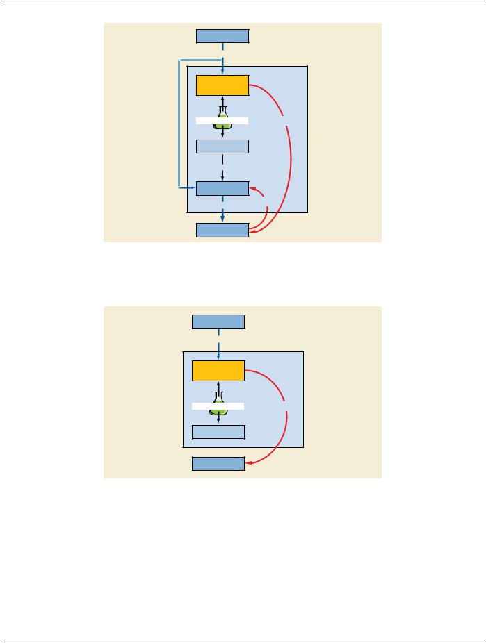
FigureOOO-2demonstratesaHotLabmanagementsystemastheRRDcreator.Itrecordstheactivityamountandtheadministration​ time. It creates the RRD report and sends it to the modality. Consistent time is required to accurately communicate activity amount.​ The consistent time region highlights systems and steps where accurate time reporting is essential. A DICOM Store moves the report​ to the modality.​

- Standard -​

Page 640​

DICOM PS3.17 2020a - Explanatory Information​

Procedure Orders

DICOM Worklist

Consistent Time

Hot Lab

Management

System

Radiopharmaceutical

RRD SR

Radiopharmaceutical

Administered

Patient Scanned

Modality

RRD SR

DICOM

Image Archive

Figure OOO-2. Hot Lab Management System as the RRD Creator​

Figure OOO-3 demonstrates RRD workflow where a radiopharmaceutical is administered to a patient for a non-imaging procedure.​ The report is sent to the image manager/image archive for storage and reporting.​

Procedure Orders

DICOM Worklist

Consistent Time

Hot Lab

Management

System

Radiopharmaceutical

RRD SR

Radiopharmaceutical

Administered

Image Archive

Figure OOO-3. Workflow for a Non-imaging Procedure​

Figure OOO-4 demonstrates when an infusion system or a radioisotope generator is the RRD creator.​

- Standard -​

Источник: https://studfile.net/preview/14585770/