Материал: part17

Внимание! Если размещение файла нарушает Ваши авторские права, то обязательно сообщите нам

DICOM PS3.17 2020a - Explanatory Information​

Page 641​

Procedure Orders

DICOM Worklist

Consistent Time

Hot Lab


Management


System


Radiopharmaceutical

Radiopharmaceutical


infusion system or


radioisotope generator


RRD SR

Patient Scanned


Modality


DICOM

RRD SR


Image Archive


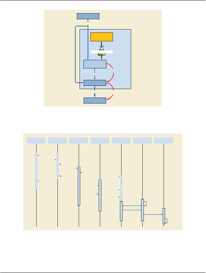
Figure OOO-4. Workflow for an Infusion System or a Radioisotope Generator​

FigureOOO-5isaUMLsequencediagramtoillustratestepsforcreationanddownstreamusecaseforRadiopharmaceuticalRadiation​

DosereportandCTdosereportforthePET-CTsystem.TheRRDisstoredtoanimagearchiveandretrievedbythePET-CTscanner.​

Workstation


RRD Creator


Patient


PET\CT Modality


Image Mgr\Archive


Dose Information


Dose Register

Provider


Reporter


Worklist Query


Procedure Steps


Dose Assayed


Product Administered


Uptake


Does Assayed


Store RRD SR


Worklist Query


Procedure Steps


Query RRD SR


PET\CT Performed


Retrieve RRD SR


CT Dose SR


Start Report Task

Query Dose Reports

Retrieve Reports

Submit Reports

Perform Analysis

Figure OOO-5. UML Sequence Diagram for Typical Workflow​

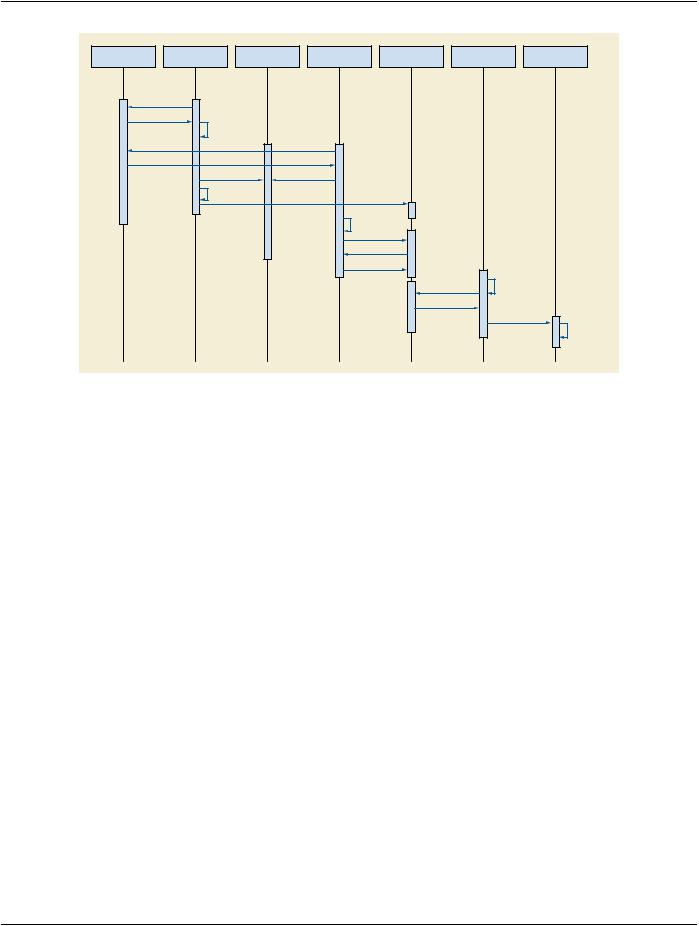
Figure OOO-6 is a UML sequence diagram to illustrate steps for creation and downstream use for radiopharmaceutical that is admin-​ istered when the modality starts acquisition. The diagram illustrates that the dose report is reconciled with the image at later time by​ an image processing step.​

- Standard -​

Page 642​

DICOM PS3.17 2020a - Explanatory Information​


Workstation

RRD Creator

Patient

NM Modality

Image Mgr\Archive

Dose Information

Dose Register

Provider

Reporter


Worklist Query


Procedure Steps

Dose Assayed


Worklist Query


Procedure Steps


Product Administered

Acq. Start


Does Assayed


Store RRD SR


Process images


Query RRD SR


Retrieve RRD SR


Store Images


Start Report Task


Query Dose Reports


Retrieve Reports


Submit Reports

Perform Analysis

Figure OOO-6. UML Sequence Diagram for when Radiopharmaceutical and the Modality are Started at​ the Same Time​

OOO.3Real-WorldRadiopharmaceuticalandRadiopharmaceuticalComponents​

Identification​

The Radiopharmaceutical Radiation Dose (RRD) template provides a means to report the radiopharmaceutical identification number​ and the identification numbers of its components.​

A typical use case is that when a radio-pharmacist elutes a radionuclide from a generator into a vial. The radionuclide elution is given​ an identification number (Radionuclide Vial Identifier). The pharmacists then draws some radionuclide from the vial to compound with​ areagent(ReagentVialIdentifier)creatingamultidosevialofaradiopharmaceutical.Themultidosevialisgivenidentificationnumber​ (Radiopharmaceutical Lot Identifier). Individual doses are drawn from the multidose vial for administration to patients. Each of the​ doses is given an identification number (Radiopharmaceutical Identifier).​

A second use case is that when a patient is prescribed 2 MBq of an oral radiopharmaceutical. The radio-pharmacist dispenses two​ 1MBqcapsules.Eachcapsulemayhavedifferentlotnumber(RadiopharmaceuticalLotIdentifier).Thetwocapsulesareadministered​ at the same time as one dose (Radiopharmaceutical Identifier). The report may contain two Radiopharmaceutical Lot Identifiers one​ for each capsule and one radiopharmaceutical identifier for the dose.​

Figure OOO-7 is a diagram the displays the hierarchical relationship between the radiopharmaceutical dispense unit identifier, radio-​ pharmaceutical lot identifier, reagent vial identifier and the radionuclide vial identifier.​

- Standard -​

DICOM PS3.17 2020a - Explanatory Information​

Page 643​

Radiopharmaceutical

Dispense Unit Identifier

Radiopharmaceutical

Lot Identifier

Radionuclide

Reagent

Vial Identifier

Vial Identifier


Figure OOO-7. Radiopharmaceutical and Radiopharmaceutical Component Identification Relationship​

- Standard -​

Page 644​

DICOM PS3.17 2020a - Explanatory Information​

- Standard -​

DICOM PS3.17 2020a - Explanatory Information​

Page 645​

PPP Examples of Communication of Display​

Parameters (Informative)​

PPP.1 The Relationship Between AE and Display System​

The Display System SCU and the Display System SCP are peer DICOM Communication of Display Parameters management applic-​ ation entities. The application entity of the Display System SCP supports one or more display subsystems.​

Display System SCU and the SCP establish an association by using the association services of the OSI upper layer service.​

While the association is being established, each of application entity negotiates the supported SOP classes.​

PPP.2 Examples of Message Sequencing​

This section provides an examples of message sequencing when using the Display System SOP Class. This section is not intended​ to provide an exhaustive set of use cases but rather an informative example. There are other valid message sequences that could​ be used to obtain an equivalent outcome.​

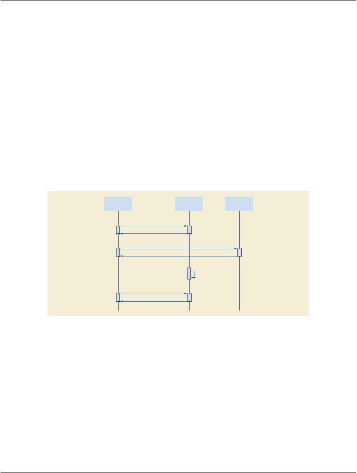
PPP.2.1 Example of Retrieval of Status and Configuration From Display Systems​

QC


Display


Display

Management


System A


System B

Station


Gets Display System Status and Configuration

Gets Display System Status and Configuration

Changes Status

Gets Display System Status

Figure PPP.2.1-1. Example of System Status and Configuration Message Sequencing​

QC Management Station: Manages display systems status and Configurations. This works as an SCU.​

Display System A and B: Have display devices. Each display device may be other display vendors'. These work as SCPs.​ Generation and notification of change events are out of a scope of DICOM.​

PPP.3 Examples of Display System SOP Class​

PPP.3.1 An Example of A Typical Display System​

A typical Display System is shown in Figure PPP.3.1-1.​

- Standard -​

Источник: https://studfile.net/preview/14585770/