Материал: part17
DICOM PS3.17 2020a - Explanatory Information |
Page 221 |
T Quantitative Analysis References (Informative)
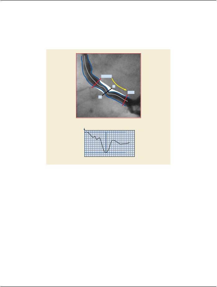
T.1 Definition of Left and Right in the Case of Quantitative Arterial Analysis
Proximal
L
Distal
R
Diameter
(mm)
4.27
1.01
Proximal  Distal
Figure T.1-1. Definition of Left and Right in the Case of Quantitative Arterial Analysis
T.2 Definition of Diameter Symmetry with Arterial Plaques
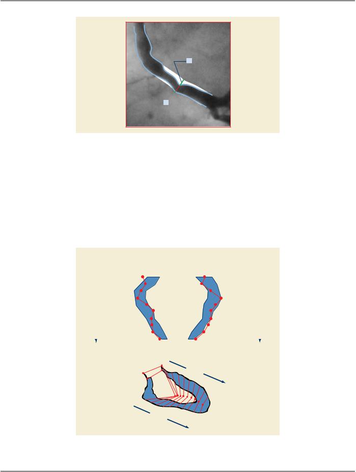
The Diameter Symmetry of a Stenosis is a parameter determining the symmetry in arterial plaque distribution.
- Standard -
Page 222 |
DICOM PS3.17 2020a - Explanatory Information |
b
a 
Figure T.2-1. Definition of Diameter Symmetry with Arterial Plaques
The Symmetry Index is defined by: a / b where a is smaller or equal to than b. a and b are measured in the reconstructed artery at the position of the minimal luminal diameter.
Possible values of symmetry range from 0 to 1, where 0 indicates complete asymmetry and 1 indicates complete symmetry.
Reference: Quantitative coronary arteriography; physiological aspects, page 102-103 in: Reiber and Serruys, Quantitative coronary arteriography, 1991
T.3 Wall Motion Regions
T.3.1 Landmark Based Wall Motion Regions
Landmark-based Wall Motion
Contributions of Regions to global Ejection Fraction (CREF)
|
|
|
|
|
|
|
|
|
|
|
|
4.9 |
3.5 |
|
|
|
|
|
|
|
|
|
|
|
|
|
11 |
|
|
|
|
|
|
|
|
|
|
|
|
|
|
|
1 |
|
|
||||
|
|
|
|
|
|
|
|
|
|
|
|
|
|
|
|
|
|
|
|
|
|
|||
|
|
Post. Basal |
|
|
|
|
|
|
|
4.0 |
3.0 |
|
|
|
|
|
|
|
Ant. Basal |
|
|
|||
|
|
22.7% |
|
|
|
|
|
|
|
|
|
|
|
|
|
|
|
|
|
|
19.9% |
|
|
|
|
|
|
|
|
|
|
|
|
|
|
5.5 |
4.4 |
|
|
|
|
|
|
|
|
|
|
||
|
|
|
|
|
|
|
|
|
|
|
5.9 |
6.3 |
|
|
|
|
|
|
|
|
|
|
||
|
|
|
|
|
|
|
|
|
|
|
|
4.2 |
5.4 |
|
|
|
|
|
|
|
|
|
|
|
|
|
15 |
|
|
|
|
|
|
|
|
|
|
|
|
|
|
|
5 |
|
|
||||
Segments |
|
|
|
|
|
|
|
|
|
|
|
|
|
|
|
|
|
|
Segments |
|||||
Diaphragmatic |
|
|
|
|
|
|
|
2.9 |
4.4 |
|
|
|
|
|
|
|
Ant. Lateral |
|||||||
11-20 |
10.5% |
|
|
|
|
|
|
|
|
|
|
|
|
|
|
17.3% |
1-10 |
|||||||
|
|
|
|
|
|
|
|
|
|
|
|
|
|
|
|
|
|
|||||||
|
|
|
|
|
|
|
|
|
|
|
3.4 |
4.5 |
|
|
|
|
|
|
|
|
|
|
||
|
|
|
|
|
|
|
|
|
|
|
|
|
|
|
|
|
|
|
|
|
||||
|
|
|
|
|
|
|
|
|
|
|
3.4 |
4.0 |
|
|
|
|
|
|
|
|
|
|
||
|
|
|
|
|
|
|
|
|
|
|
|
3.3 |
3.3 |
|
|
|
|
|
|
|
|
|
|
|
|
|
19 |
|
|
|
|
|
|
|
|
|
|
|
|
|
|
|
9 |
|
|
||||
|
|
|
|
|
|
|
|
|
|
|
|
|
|
|
|
|
|
|
|
|
|
|||
|
|
Apical |
|
|
|
|
|
|
|
1.9 |
1.9 |
|
|
|
|
|
|
|
|
|
|
|||
|
|
7.1% |
|
|
|
|
|
|
|
|
|
|
|
|
|
|
|
|
|
|
|
|
|
|
|
|
|
|
|
|
|
|
|
|
|
|
|
|
|
|
|
|
|
|
|
|
|
|
|
|
|
|
% |
7 |
6 |
5 |
4 |
3 |
2 |
1 |
0 |
0 |
1 |
2 |
3 |
4 |
5 |
6 |
7 |
% |
|
|
||
1 |
Segments 5 1-10
9
11
15 |
|
Segments |
19 |
11-20 |
|
Figure T.3-1. Landmark Based Wall Motion Regions
- Standard -
DICOM PS3.17 2020a - Explanatory Information |
Page 223 |
To compare the quantitative results with those provided by the usual visual interpretation, the left ventricular boundary is divided into 5 anatomical regions, denoted:
•Anterobasal.
•Anterolateral.
•Posterobasal.
•Diaphragmatic.
•Apical.
T.3.2 Centerline Wall Motion Region
Centerline Wall Motion
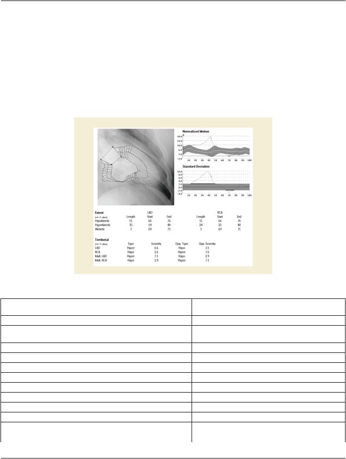
Figure T.3-2. Example of Centerline Wall Motion Template Usage
Node |
Code Meaning of Concept Name |
Code Meaning or Example |
TID |
|
|
|
Value |
|
|
X.X |
Findings |
|
|
|
X.X.1 |
Procedure Reported |
Centerline Wall Motion |
TID 3208 |
|
|
|
Analysis |
|
|
X.X.2 |
Contour Realignment |
Center of Gravity |
TID 3208 |
|
X.X.3 |
Normalized Chord Length |
5.0 % |
TID 300 |
|
X.X.4 |
Normalized Chord Length |
5.1 % |
TID 300 |
|
X.X.5 |
Normalized Chord Length |
5.3 % |
TID 300 |
|
… |
… |
… |
… |
|
X.X.102 |
Normalized Chord Length |
4.5 % |
TID 300 |
|
X.X.103 |
Threshold Value |
2 |
TID 3208 |
|
X.X.104 |
Abnormal Region |
|
TID 3208 |
|
X.X.104.1 |
Cardiac Wall Motion |
Hypokinetic |
TID 3208 |
|
X.X.104.2 |
Circumferential Extend |
LAD Region |
TID 3208 |
|
- Standard -

Page 224 |
DICOM PS3.17 2020a - Explanatory Information |
|
|
|
Node |
Code Meaning of Concept Name |
Code Meaning or Example |
TID |
|
|
|
Value |
|
|
X.X.104.3 |
First Chord of Abnormal Region |
66 |
TID 3208 |
|
X.X.104.4 |
Last Chord of Abnormal Region |
76 |
TID 3208 |
|
X.X.104.5 |
Cardiac Wall Motion |
Hypokinetic |
TID 3208 |
|
X.X.104.6 |
Circumferential Extend |
RCA Region |
TID 3208 |
|
X.X.104.7 |
First Chord of Abnormal Region |
66 |
TID 3208 |
|
X.X.104.8 |
Last Chord of Abnormal Region |
76 |
TID 3208 |
|
X.X.104.9 |
Cardiac Wall Motion |
Hyperkinetic |
TID 3208 |
|
X.X.104.10 |
Circumferential Extend |
LAD Region |
TID 3208 |
|
X.X.104.11 |
First Chord of Abnormal Region |
14 |
TID 3208 |
|
X.X.104.12 |
Last Chord of Abnormal Region |
48 |
TID 3208 |
|
X.X.104.13 |
Cardiac Wall Motion |
Hyperkinetic |
TID 3208 |
|
X.X.104.14 |
Circumferential Extend |
RCA Region |
TID 3208 |
|
X.X.104.15 |
First Chord of Abnormal Region |
25 |
TID 3208 |
|
X.X.104.16 |
Last Chord of Abnormal Region |
48 |
TID 3208 |
|
X.X.104.17 |
Cardiac Wall Motion |
Akinetic |
TID 3208 |
|
X.X.104.18 |
Circumferential Extend |
LAD Region |
TID 3208 |
|
X.X.104.19 |
First Chord of Abnormal Region |
69 |
TID 3208 |
|
X.X.104.20 |
Last Chord of Abnormal Region |
71 |
TID 3208 |
|
X.X.104.21 |
Cardiac Wall Motion |
Akinetic |
TID 3208 |
|
X.X.104.22 |
Circumferential Extend |
RCA Region |
TID 3208 |
|
X.X.104.23 |
First Chord of Abnormal Region |
69 |
TID 3208 |
|
X.X.104.24 |
Last Chord of Abnormal Region |
71 |
TID 3208 |
|
X.X.105 |
Regional Abnormal Wall Motion |
|
TID 3208 |
|
X.X.105.1 |
Finding Site |
Single LAD Region in RAOTID 3208 |
|
|
|
|
Projection |
|
|
X.X.105.2 |
Territory Region Severity |
6.6 |
TID 300 |
|
X.X.105.2.1 |
Cardiac Wall Motion |
Hypokinetic |
TID 300 |
|
X.X.105.3 |
Opposite Region Severity |
3.1 |
TID 300 |
|
X.X.105.3.1 |
Cardiac Wall Motion |
Hyperkinetic |
TID 300 |
|
X.X.105.4 |
Finding Site |
Single RCA Region in RAOTID 3208 |
|
|
|
|
Projection |
|
|
X.X.105.5 |
Territory Region Severity |
2.6 |
TID 300 |
|
X.X.105.5.1 |
Cardiac Wall Motion |
Hyperkinetic |
TID 300 |
|
X.X.105.6 |
Opposite Region Severity |
7.6 |
TID 300 |
|
X.X.105.6.1 |
Cardiac Wall Motion |
Hypokinetic |
TID 300 |
|
X.X.105.7 |
Finding Site |
Multiple LAD Region in RAOTID 3208 |
|
|
|
|
Projection |
|
|
X.X.105.8 |
Territory Region Severity |
7.1 |
TID 300 |
|
X.X.105.8.1 |
Cardiac Wall Motion |
Hyperkinetic |
TID 300 |
|
X.X.105.9 |
Opposite Region Severity |
2.9 |
TID 300 |
|
X.X.105.9.1 |
Cardiac Wall Motion |
Hyperkinetic |
TID 300 |
|
- Standard -
|
DICOM PS3.17 2020a - Explanatory Information |
|
Page 225 |
|||
Node |
Code Meaning of Concept Name |
Code Meaning or Example |
TID |
|||
|
|
|
|
Value |
|
|
X.X.105.10 |
Finding Site |
|
|
MultipleRCAinRegionRAOTID 3208 |
|
|
|
|
|
|
Projection |
|
|
X.X.105.11 |
Territory Region Severity |
2.9 |
TID 300 |
|
||
X.X.105.11.1 |
Cardiac Wall Motion |
|
Hypokinetic |
TID 300 |
|
|
X.X.105.12 |
Opposite Region Severity |
7.1 |
TID 300 |
|
||
X.X.105.12.1 |
Cardiac Wall Motion |
|
Hyperkinetic |
TID 300 |
|
|
X.X 106 |
… |
|
|
… |
TID 3208 |
|
T.3.4 Radial Based Wall Motion Region |
|
|
|
|||
|
|
|
Radial-based Wall Motion |
|
|
|
|
Mean Motion |
|
|
|
|
|
|
1. Antero-basal |
: |
33% |
|
|
|
|
2. Antero-lateral |
: |
39% |
|
|
|
|
3. Apical |
: |
17% |
1 |
|
|
4.Diaphragmatic : 26%
5.Postero-basal : 30%
2
5
4
3
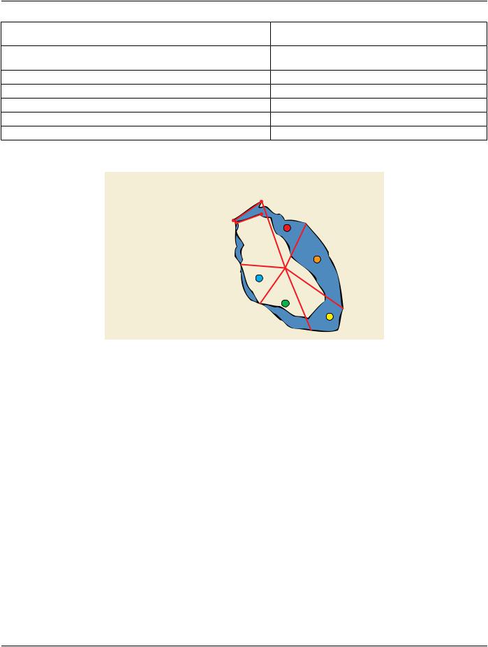
Figure T.3-3. Radial Based Wall Motion Region
T.4 Quantitative Arterial Analysis Reference Method
Defined Terms:
•Computer Calculated Reference.
•Interpolated Local Reference.
•Mean Local Reference.
T.4.1 Computer Calculated Reference
Thecomputer-definedobstructionanalysiscalculatesthereconstructiondiameterbasedonthediametersoutsidethestenoticsegment. This method is completely automated and user independent. The reconstructed diameter represents the diameters of the artery had the obstruction not been present.
The proximal and distal borders of the stenotic segment are automatically calculated.
The difference between the detected contour and the reconstructed contour inside the reconstructed diameter contour is considered to be the plaque.
Based on the reconstruction diameter at the Minimum Luminal Diameter (MLD) position a reference diameter for the obstruction is defined.
- Standard -