Материал: part17
Page 226 |
DICOM PS3.17 2020a - Explanatory Information |
T.4.2 Interpolated Reference
The interpolated reference obstruction analysis calculates a reconstruction diameter for each position in the analyzed artery. This reconstructed diameter represents the diameters of the artery when no disease would be present. The reconstruction diameter is a line fitted through at least two user-defined reference markers by linear interpolation.
By default two references are used at the positions of the reference markers are automatically positioned at 5% and 95% of the artery length.
To calculate a percentage diameter stenosis the reference diameter for the obstruction is defined as the reconstructed diameter at the position of the MLD.
In cases where the proximal and distal part of the analyzed artery have a stable diameter during the treatment and long-term follow- up, this method will produce a stable reference diameter for all positions in the artery.
T.4.3 Mean Local Reference
In case of mean local reference obstruction the reference diameter will be an average of the diameters at the position of one or more the reference markers.
This method is particularly appropriate for the analysis of bifurcated arteries.
T.5 Positions in Diameter Graphic
A vessel segment length as seen in the image is not always indicated as the same X-axis difference in the graph.
The X-axis of the graph is based on pixel positions on the midline and these points are not necessarily equidistant. This is caused by the fact that vessels do not only run perfectly horizontally or vertically, but also at angles.
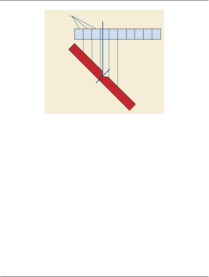
When a vessel midline is covering a number of pixel positions perfectly horizontal or vertical, it will cover less space in mm compared to a vessel that covers the same number of pixel positions under an angle. When a segment runs perfectly horizontal or vertical, the segment length is equal to the amount of midline pixel points times the pixel separation (each point of the midline is separated exactly the pixel spacing in mm) and the points on the X-axis also represent exactly one pixel space. This is not the case when the vessel runs under an angle. For example an artery that is positioned at a 45 angle, the distance between two points on the midline is 0.7 times the pixel spacing.
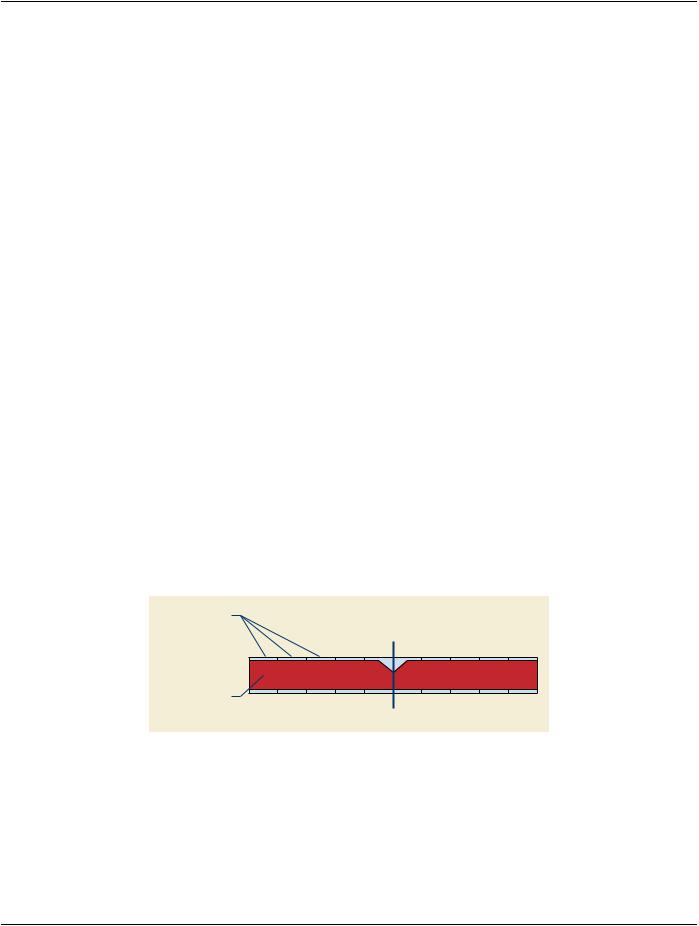
As example, the artery consists of 10 elements (n =10); each has a length of 1mm (pixel size). If the MLD was exactly in the center of the artery you would expect the length from 0 to the MLD would be 5 sub segments long, thus 5 mm. This is true if the artery runs horizontal or vertically (assumed aspect ratio is 1).
pixel elements
0 |
1 |
2 |
3 |
... |
n |
artery |
|
|
|
|
|
MLD
Figure T.5-1. Artery Horizontal
If the artery is positioned in a 45º angle then the length of each element is √2 times the pixel size compared to the previous example. Thus the length depends on the angle of the artery.
- Standard -
DICOM PS3.17 2020a - Explanatory Information |
Page 227 |
pixel elements
0 |
1 |
2 |
3 |
... |
n |
artery
Figure T.5-2. Artery 45º Angle
- Standard -

Page 228 |
DICOM PS3.17 2020a - Explanatory Information |
- Standard -

DICOM PS3.17 2020a - Explanatory Information |
Page 229 |
U Ophthalmology Use Cases (Informative)
U.1 Ophthalmic Photography Use Cases
The following use cases are examples of how the DICOM Ophthalmology Photography objects may be used. These use cases utilize the term "picture" or "pictures" to avoid using the DICOM terminology of frame, instance or image. In the use cases, the series means DICOM Series.
U.1.1 Routine N-spot Exam
An N-spot retinal photography exam means that "N" predefined locations on the retina are examined.
AroutineN-spotretinalphotographyexamisorderedforbotheyes.Thereisnothingunusualobservedduringtheexam,soNpictures are taken of each retina. This healthcare facility also specifies that in an N-spot exam a routine external picture is captured of both eyes, that the current intraocular pressure (IOP) is measured, and that the current refractive state is measured.
The resulting study contains:
a.2N pictures of the retina and one external picture. Each retinal picture is labeled in the acquisition information to indicate its pos- ition in the local N-spot definition. The series is not labeled, each picture is labeled OS or OD as appropriate.
Note
DICOMusesL,R,andBintheImageLateralityAttribute(0020,0062).TheactualencodingswillbeL,R,orB.Ophthalmic equipment can convert this to OS, OD, and OU before display.
b.In the acquisition information of every picture, the IOP and refractive state information is replicated.
c.Since there are no stereo pictures taken, there is no Stereometric Relationship IOD instance created.
The pictures may or may not be in the same Series.
U.1.2 Routine N-spot Exam With Exceptions
A routine N-spot retinal photography exam is ordered for both eyes. During the exam a lesion is observed in the right eye. The lesion spans several spots, so an additional wide angle view is taken that captures the complete lesion. Additional narrow angle views of the lesion are captured in stereo. After completing the N-spot exam, several slit lamp pictures are taken to further detail the lesion outline.
The resulting study contains:
a.2N pictures of the retina and one external picture, one additional wide angle picture of the abnormal retina, 2M additional pictures for the stereo detail of the abnormal retina, and several slit lamp pictures of the abnormal eye. The different lenses and lighting parameters are documented in the acquisition information for each picture.
b.One instance of a Stereometric Relationship IOD, indicating which of the stereo detail pictures above should be used as stereo pairs.
The pictures may or may not be in the same Series.
U.1.3 Routine Flourescein Exam
A routine fluorescein exam is ordered for one eye. The procedure includes:
a.Routine stereo N-spot pictures of both eyes, routine external picture, and current IOP.
b.Reference stereo picture of each eye using filtered lighting
c.Fluorescein injection
- Standard -

Page 230 |
DICOM PS3.17 2020a - Explanatory Information |
d.Capture of 20 stereo pairs with about 0.7 seconds between pictures in a pair and 3-5 seconds between pairs.
e.Stereo pair capture of each eye at increasing intervals for the next 10 minutes, taking a total of 8 pairs for each eye.
The result is a study with:
a.The usual 2N+1 pictures from the N-spot exam
b.Four pictures taken with filtered lighting (documented in acquisition information) that constitute a stereo pair for each eye.
c.40 pictures (20 pairs) for one eye of near term fluorescein. These include the acquisition information, lighting context, and time stamp.
d.32pictures(8pairsforeacheye)oflongtermfluorescein.Theseincludeacquisitioninformation,lightingcontext,andtimestamp.
e.One Stereometric Relationship IOD, indicating which of the above OP instances should be used as stereo pairs.
The pictures of a) through d) may or may not be in the same series.
U.1.4 External Examination
The patient presents with a generic eye complaint. Visual examination reveals a possible abrasion. The general appearance of the eyes is documented with a wide angle shot, followed by several detailed pictures of the ocular surface. A topical stain is applied to reveal details of the surface lesion, followed by several additional pictures. Due to the nature of the examination, no basic ophthalmic measurements were taken.
The result is a study with one or more series that contains:
a.One overall external picture of both eyes
b.Several close-up pictures of the injured eye
c.Several close-up pictures of the injured eye after topical stain. These pictures have the additional stain information conveyed in the acquisition information for these pictures.
U.1.5 External Examination With Intention
The patient is suspected of a nervous system injury. A series of external pictures are taken with the patient given instructions to follow a light with his eyes. For each picture the location of the light is indicated by the patient intent information, (e.g., above, below, patient left, patient right).
The result is a study with one or more series that contains:
a.Individual pictures with each picture using the patient intent field to indicate the intended direction.
U.1.6 External Examination With Drug Application
Patient is suspected of myaesthenia gravis. Both eyes are imaged in normal situation. Then after Tensilon® (edrophonium chloride) injection a series of pictures is taken. The time, amount, and method of Tensilon® (edrophonium chloride) administration is captured in the acquisition information. The time stamps of the pictures are used in conjunction with the behavior of the eyelids to assess the state of the disease.
Note
Tensilon® is a registered trademark of Roche Laboratories.
The result is a study with one or more series that contains:
a.Multiple reference pictures prior to test
b.Pictures with acquisition information to document drug administration time.
- Standard -