Материал: part17

Внимание! Если размещение файла нарушает Ваши авторские права, то обязательно сообщите нам

Page 486​

DICOM PS3.17 2020a - Explanatory Information​

R

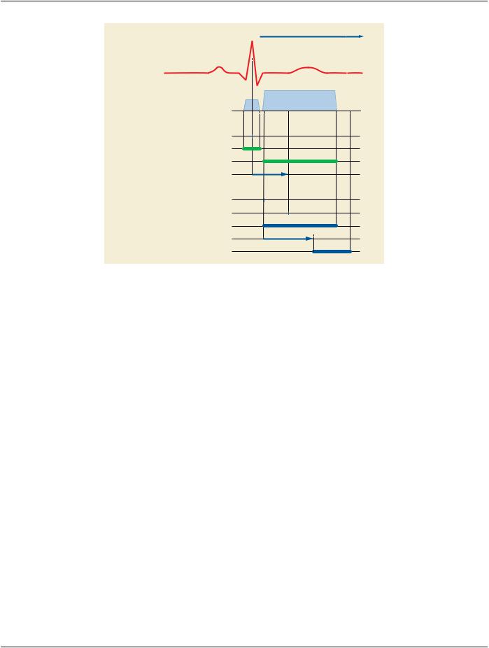
time

Last R peak prior to X-Ray Frame “i”

Pre-Frame X-Ray

Frame X-Ray

Nominal Cardiac Trigger Delay Time (0020,9153)

Frame Acquisition Number (0020,9156) = “i”

Frame i Acquisition DateTime (0018,9074)

Frame i Reference DateTime (0018,9151)

Frame i Acquisition Duration (0018,9220)

Detector Activation Offset from Exposure (0018,7016)

Detector Activation Time (0018,7014)

Figure FFF.1.1-2. Time Relationships of one Frame​

Note​

1.​Positioner angle values, table position values etc… are measured at the Frame Reference DateTime.​

2.​Dose of the frame is the cumulative dose: PRE-FRAME + FRAME.​

FFF.1.2 Acquisition Geometry​

This chapter illustrates the relationships between the geometrical models of the patient, the table, the positioner, the detector and the​ pixel data.​

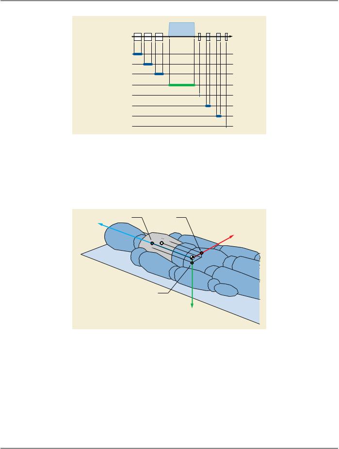
ThefollowingfigureshowsthedifferentstepsintheX-Rayacquisitionthatinfluencesthegeometricalrelationshipbetweenthepatient​ and the pixel data.​

- Standard -​

DICOM PS3.17 2020a - Explanatory Information​

Page 487​

time

PATIENT positioning

TABLE movement

POSITIONER movement

X-Ray Acquisition

FOV image creation

FOV rotation

FOV Horizontal flip

Pixel Data Creation

Figure FFF.1.2-1. Acquisition Steps Influencing the Geometrical Relationship Between the Patient and​ the Pixel Data​

FFF.1.2.1 Patient Description​

Refer to Annex A for the definition of the patient orientation.​

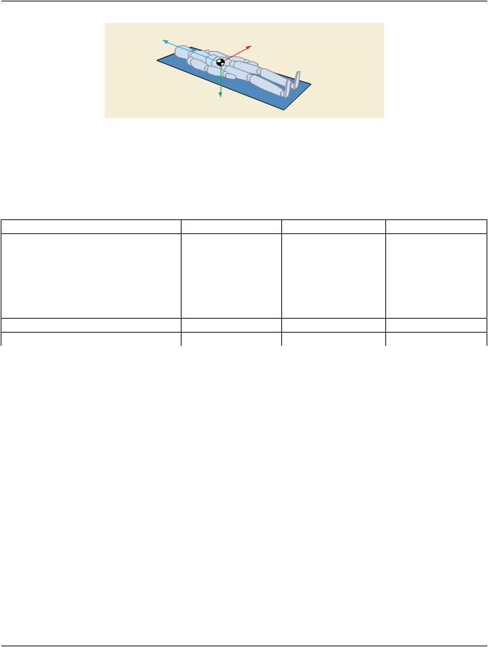
A point of the patient is represented as: P = (Pleft, Pposterior, Phead).​

Head

Phead

Pleft

Left

P

Pposterior

Posterior

Figure FFF.1.2-2. Point P Defined in the Patient Orientation​

FFF.1.2.2 Patient Position​

FFF.1.2.2.1 Table Description​

The table coordinates are defined in Section C.8.7.4.1.4 “Table Motion With Patient in Relation to Imaging Chain” in PS3.3.​

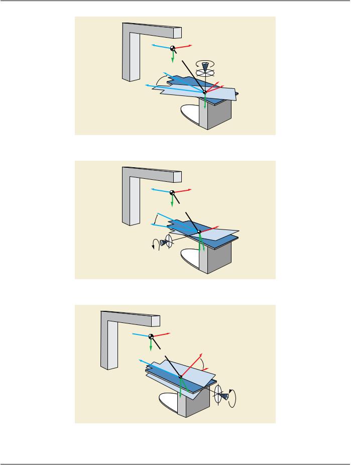
The table coordinate system is represented as: (Ot, Xt, Yt, Zt) where the origin Ot is located on the tabletop and is arbitrarily defined​ for each system.​

- Standard -​

Page 488​

DICOM PS3.17 2020a - Explanatory Information​

+ Zt

+ Xt

Table Head

Table Left

Table Right

Table Top Plane

Table Foot

+ Yt

Figure FFF.1.2-3. Table Coordinate System​

FFF.1.2.2.2 Options For Patient Position On The X-Ray Table​

The position of the patient in the X-Ray table is described in Section C.7.3.1.1.2 “Patient Position” in PS3.3.​

The table below shows the direction cosines for each of the three patient directions (Left, Posterior, Head) related to the Table co-​ ordinate system (Xt, Yt, Zt), for each patient position on the X-Ray table:​

Patient Position​

Patient left direction​ Patientposteriordirection​Patient head direction​

Recumbent - Head First - Supine​

(1, 0, 0)​

(0, 1, 0)​

(0, 0, 1)​

Recumbent - Head First - Prone​

(-1, 0, 0)​

(0, -1, 0)​

(0, 0, 1)​

Recumbent - Head First - Decubitus Right​

(0, -1, 0)​

(1, 0, 0)​

(0, 0, 1)​

Recumbent - Head First - Decubitus Left​

(0, 1, 0)​

(-1, 0, 0)​

(0, 0, 1)​

Recumbent - Feet First - Supine​

(-1, 0, 0)​

(0, 1, 0)​

(0, 0, -1)​

Recumbent - Feet First - Prone​

(1, 0, 0)​

(0, -1, 0)​

(0, 0, -1)​

Recumbent - Feet FirstDecubitus Right​

(0, -1, 0)​

(-1, 0, 0)​

(0, 0, -1)​

Recumbent - Feet First -Decubitus Left​

(0, 1, 0)​

(1, 0, 0)​

(0, 0, -1)​

FFF.1.2.3 Table Movement​

FFF.1.2.3.1 Isocenter Coordinate System​

The Isocenter coordinate system is defined in Section C.8.19.6.13.1.1 “Isocenter Coordinate System” in PS3.3.​

FFF.1.2.3.2 Table Movement in The Isocenter Coordinate System​

The table coordinate system is defined in Section C.8.19.6.13.1.3 “Table Coordinate System” in PS3.3 where the table translation is​ represented as (TX,TY,TZ). The table rotation is represented as (At1, At2, At3).​

- Standard -​

DICOM PS3.17 2020a - Explanatory Information​

Page 489​

+Z

O

+X


(Tx, Ty, Tz)


+Y


Z


Zt


At1, Table Horizontal


Ot

Rotation Angle


Y, Y t

Axis of Rotation

Xt

X

Figure FFF.1.2-4. At1: Table Horizontal Rotation Angle​

+Z

+Y

Z

Zt

At2, Table Head Tilt Angle

O

(Tx,

+X

Ty, Tz)

Ot

X, Xt

Axis of Rotation

Y

Yt


Figure FFF.1.2-5. At2: Table Head Tilt Angle​

+Z

Z, Zt


O

+X

+Y

(Tx, Ty, Tz)


Ot

Xt

At3, Table Cradle Tilt Angle

X

Yt

Y

Axis of Rotation

Figure FFF.1.2-6. At3: Table Cradle Tilt Angle​

- Standard -​

Page 490​

DICOM PS3.17 2020a - Explanatory Information​

A point (P Xt , P Yt , P Zt ) in the table coordinate system (see Figure FFF.1.2-7) can be expressed as a point (P X , P Y , P Z ) in the​ Isocenter coordinate system by applying the following transformation:​

(PX, PY, PZ)T= (R3 .R2 .R1)T .(PXt, PYt, PZt)T+ (TX, TY, TZ)T​

And inversely, a point (P X , P Y , P Z ) in the Isocenter coordinate system can be expressed as a point (P Xt , P Yt , P Zt ) in the table​ coordinate system by applying the following transformation:​

(PXt, PYt, PZt)T= (R3 .R2 .R1).((PX, PY, PZ)T- (TX, TY, TZ)T)​

Where R1 , R2 and R3 are defined in Figure FFF.1.2-7.​


)

0

−sin(At


)


cos(At

1

1


R1

=


0


1

0


sin(At1)

0

cos(At1)


0


0


1


R2

= 0

cos(At2)

sin(At2)


0 −sin(At2) cos(At2)


0


cos(At3) −sin(At3)


R3

= sin(At3)

cos(At3)

0


0


0

1

Figure FFF.1.2-7. Point P in the Table and Isocenter Coordinate Systems​

FFF.1.2.4 Positioner Movement​

FFF.1.2.4.1 Positioner Movement in The Isocenter Coordinate System​

The positioner coordinate system is defined in Section C.8.19.6.13.1.2 “Positioner Coordinate System” in PS3.3 where the positioner​ angles are represented as (Ap1, Ap2, Ap3).​

A point (P Xp , P Yp , P Zp ) in the positioner coordinate system can be expressed as a point (P X , P Y , P Z ) in the Isocenter coordinate​ system by applying the following transformation:​

(PX, PY, PZ)T= (R2 .R1)T .(R3 T .(PXp, PYp, PZp)T)​

And inversely, a point (P X , P Y , P Z ) in the Isocenter coordinate system can be expressed as a point (P Xp , P Yp , P Zp ) in the po-​ sitioner coordinate system by applying the following transformation:​

(PXp, PYp, PZp)T= R3 .((R2 .R1).(PX, PY, PZ)T)​

Where R1 ,R2 andR3 are defined as follows:​

FFF.1.2.4.2 X-Ray Incidence and Image Coordinate System​

The following concepts illustrate the model of X-Ray cone-beam projection:​

The X-Ray incidence represents the vector going from the X-Ray source to the Isocenter.​

The receptor plane represents the plane perpendicular to the X-Ray Incidence, at distance SID from the X-Ray source. Applies for​ both image intensifier and digital detector. In case of digital detector it is equivalent to the detector plane.​

The image coordinate system is represented by (o, u, v), where "o" is the projection of the Isocenter on the receptor plane.​

The source to isocenter distance is called ISO. The source image receptor distance is called SID.​

The projection of a point (P Xp , P Yp , P Zp ) in the positioner coordinate system is represented as a point (P u , P v ) in the image​ coordinate system.​

- Standard -​

Источник: https://studfile.net/preview/14585770/