Материал: Разработка и прототипирование цифровых устройств на языках VHDL и Verilog. Барабанов В.Ф., Гребенникова Н.И
x <= '0'; y <= '1'; z <= '1'; c <= '0'; wait for 20 ns; x <= '0'; y <= '1'; z <= '1'; c <= '1'; wait for 20 ns; x <= '1'; y <= '0'; z <= '0'; c <= '0'; wait for 20 ns; x <= '1'; y <= '0'; z <= '0'; c <= '1'; wait for 20 ns; x <= '1'; y <= '0'; z <= '1'; c <= '0'; wait for 20 ns; x <= '1'; y <= '0'; z <= '1'; c <= '1'; wait for 20 ns; x <= '1'; y <= '1'; z <= '0'; c <= '0'; wait for 20 ns; x <= '1'; y <= '1'; z <= '0'; c <= '1'; wait for 20 ns; x <= '1'; y <= '1'; z <= '1'; c <= '0'; wait for 20 ns; x <= '1'; y <= '1'; z <= '1'; c <= '1'; wait for 20 ns;
wait;
end process;
END;
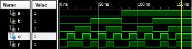
Результат моделирования:
61
ПРИЛОЖЕНИЕ 2
Пример выполнения задания лабораторной работы 2
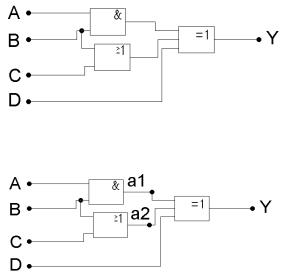
Разработать модель цифровой схемы, с использованием иерархического описания.
Для разработки модели с использованием иерархического описания выделим на схеме точки a1 и a2.
Впоследствии, при разработке иерархического описания модели необходимо создать проводники, к которым будут подключены эти промежуточные точки цифровой схемы.
Код модели на языке Verilog HDL:
`timescale 1ns / 1ps
module code_and2(input a, input b, output res); assign res = a & b;
endmodule
module code_or2(input a, input b, output res);
62
assign res = a | b; endmodule
module code_xor2(input a, input b, input c, output res); assign res = a ^ b ^ c;
endmodule
module top(input x, input y, input z, input c, output res);
wire x1, x2; |
|
|
code_and2 |
code_and2_1 |
( .x1( x ), .x2( y ), .y( x1 ) ); |
code_or2 |
code_or2_1 |
( .x1( y ), .x2( z ), .y( x2 ) ); |
code_xor2 code_xor2_1 |
( .x1( x1 ), .x2( x2 ), .x3( c ), .y( res ) |
|
); |
|
|
endmodule
Код тестовой оболочки на языке Verilog HDL: `timescale 1ns / 1ps
module top_tb;
reg [3:0] data; wire res;
top uut (
.a(data[3]),
.b(data[2]),
.c(data[1]),
.d(data[0]),
.y(res)
);
integer i; initial begin
data = 0;
63

for (i = 0; i <= 15; i=i+1) begin
#10 data = data + 1;
end
end endmodule
Результат моделирования:
Код модели на языке VHDL:
library IEEE;
use IEEE.STD_LOGIC_1164.ALL;
entity code_AND2 is
Port ( a : in STD_LOGIC; b : in STD_LOGIC; res : out STD_LOGIC);
end code_AND2;
architecture Behavioral of code_AND2 is begin
res <= a and b; end Behavioral;
library IEEE;
use IEEE.STD_LOGIC_1164.ALL; entity code_OR2 is
Port ( a : in STD_LOGIC;
64
b : in STD_LOGIC; res : out STD_LOGIC);
end code_OR2;
architecture Behavioral of code_OR2 is begin
res <= a or b; end Behavioral;
library IEEE;
use IEEE.STD_LOGIC_1164.ALL; entity my_XOR3 is
Port ( a: in STD_LOGIC;
b:in STD_LOGIC;
c:in STD_LOGIC; res: out STD_LOGIC);
end my_XOR3;
architecture Behavioral of my_XOR3 is begin
res <= a xor b xor c; end Behavioral;
library IEEE;
use IEEE.STD_LOGIC_1164.ALL;
entity code_lab2 is
Port (x: in STD_LOGIC;
y:in STD_LOGIC;
z:in STD_LOGIC;
c:in STD_LOGIC; res: out STD_LOGIC);
end code_lab2;
architecture Behavioral of code_lab2 is
65