Материал: Крючков Фундаменталс оф Нуцлеар Материалс Пхысицал Протецтион 2011
|
AZ+1 |
|
Am Z |
|
242Cm |
243Cm |
244Cm |
|
||
|
γ |
|
|
|
|
|
||||
|
|
β- |
|
|
|
|
|
|
|
|
|
A-1 |
σn,2 A |
σa |
A+1 |
|
|
|
242m |
|
|
|
Z |
α |
Z |
β+ |
Z |
|
|
|
Am |
|
|
|
|
|
|
|
|||||
|
A-4 |
|
σf |
A |
|
|
|
|
|
|
|
Z-2 |
|
|
Z-1 |
|
241Am |
242Am |
243Am |
244Am |
|
|
|
|
|
|
|
|
||||
|
|
236Pu |
237Pu |
|
238Pu |
239Pu |
240Pu |
241Pu |
242Pu |
243Pu |
|
|
|
236Np |
237Np |
238Np |
239Np |
240Np |
|
|
|
232U |
233U |
234U |
235U |
|
236U |
237U |
238U |
239U |
|
|
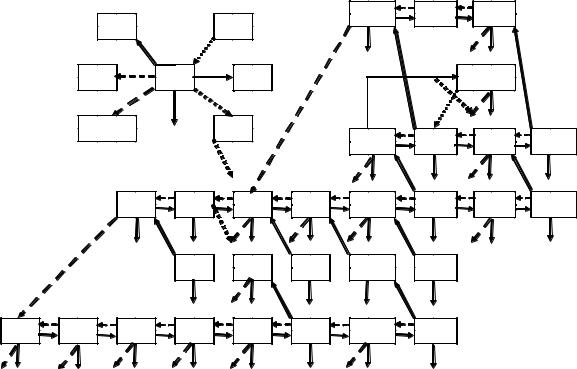
Fig. 5.3. Isotopic transformations in a uranium-plutonium cycle
231
Determination of NM content by measurements of intrinsic gamma radiations
Factors influencing NDA measurement results
NM solutions are normally homogeneous and one can simply get a standard for measurements using a suitable vessel. The content of NM in the sample is found from the intensity of its emission from the sample. Some of the gamma radiation is however absorbed inside the sample en route to the detector. The correction factor CF(АТ) that accounts for the self-absorption of NM radiation inside the sample can be found using an external gamma radiation source with an energy close to the NM radiation energy. To do this, the transmission T of the external source gamma ray beam through the sample is measured:
T = |
N |
= exp(- μl × x) , |
(5.1) |
|
|||
|
N0 |
|
|
where N0 is the number of the source-emitted gamma-quanta getting on the sample; N is the number of the source-emitted gamma-quanta transmitted through the sample; μl is the gamma-ray linear attenuation factor; and х is the sample thickness. With a plane geometry, the allowance is calculated from the formula:
CF ( AT ) = |
μl × x |
= |
- ln(T ) |
|
|
(1-T ) . |
(5.2) |
||
[1 - exp(-μl × x)] |
An extra source attached next to the detector is used to correct the counting losses caused by the measurement system’s dead time. Using a radiation source simplifies the correction circuit and makes it more reliable as compared to instrumented correction based on a pulse generator. Observations of the pulse count rate in the peak produced by this source yield data on the count losses during measurements with samples. Such source is selected such that not to hamper measurements of the NM emission from the samples.
Uranium solutions are tested via passive measurement of gamma rays with the energy of 185.7 keV of 235U, the results being corrected from the measurement results for transmission of the 75Se source radiation with the
232
energy 136.0 keV and the counting losses corrected using a (the radiation energy of 88 keV).
The range of the concentrations measured covers seven orders of magnitude. The sample dimensions are smaller than in other methods.
Waste control. Segmented gamma ray scanning
This technique is used to test containers and tanks with solid and liquid NM-containing waste. The measurement conditions in this are rather complicated: NM is present in small concentrations and has a nonuniform axial and radial distribution in the container. The volumes of the samples controlled differ greatly ranging from small vials to 200-liter metal drums. The matrix density is relatively low.
Onsite NM-containing waste is containerized in layers, NM in these being more uniform horizontally than vertically. When analyzed, the sample is rotated to mitigate the horizontal nonuniformity effects, as the vertical nonuniformity effects are mitigated by analyzing material by segments. Each segment is measured individually with all the values obtained summed up. The basic assumption is that NM is uniformly distributed inside each segment and one can determine to which extent the gamma radiations inside the segment are mitigated by measurements of the transmission.
Segmented scanning (SS) combines container movements with radiation measurements. SS is probably the most widespread ND measurement technique based on γ-radiation measurements.
Analyzed radiations
Uranium content is controlled by measuring γ-radiation of 185.7 keV. For 239Pu control, one normally measures γ-radiation of 413.7 keV.
The obtained results distorted by the absorption of γ-rays in the container are corrected with the aid of the correction factors found by measuring the transmission of the 75Se source γ-radiations with the energies of 136.0 keV, 264.6 keV, 279.5 keV and 400.6 keV through the container. The correction for the results of measuring the 185.7-keV radiation of 235U is obtained by interpolation between the transmission values for gamma ray lines with energies of 136.0 keV and 264.6 keV, while the correction for measurements of 413.7-keV 239Pu radiations is found by extrapolation.
Another source, 109Cd, (Eγ = 88.0 keV), serves to correct the pulse count errors.
233
Measurements and interpretation of results
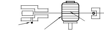
To have the result to characterize the average NM content in a container, the latter is rotated and moved vertically. The container is lifted gradually as its vertical segments are scanned, this making it possible to average the difference in attenuations of radiations in separate horizontal segments. The facility is shown schematically in Fig. 5.4.
The pulse count rate in the complete nр absorption peak is found by measurements using the formula:
n р |
= (n'р |
- RB ) × |
Rref |
, |
(5.3) |
|
|||||
|
|
|
RRL |
|
|
where n'р is the measured count rate in the interval that contains the desired
peak; (Rref /RRL) is the allowance for the counting loss found by measurements with 109Cd without and with a sample; and RB is the background count rate below the peak.
|
Shielding and |
|
|
lead collimator |
75Se source in |
|
|
shielding |
Detector |
G |
|
109Cd source |
|
|
|
Container with |
Rotating and |
|
NM in matrix |
lifting table |
Fig. 5.4. Schematic of a segmented scanning facility
The measured and corrected pulse count rate in the gamma-peak nр relates to the mass of the isotope determined via the calibration factor which is found with the aid of a standard. The contribution of the calibration factor to the systematic and random measurement error should be relatively small.
The results of measurements using a standard may be influenced by several factors, including homogeneity of the sample material, the
234
magnitude of transmission (should be over 10%), size of NM particles and others.
Segmented scanning is applicable to many low-density NM-containing materials: paper, sand, plastic, ash and liquids.
Control of deposits
Deposit is NM that remains inside process equipment and cannot be removed by way of conventional flushing. It settles in tanks and accumulates in process piping and ventilation systems. The deposit amount varies from 0.1 to 0.2% of the total facility capacity even after the equipment is cleaned thoroughly. The initial operation phase of a new facility may account for a deposit share of 1 to 10% of the output product.
Most of the uranium and plutonium deposit measurements are based on recording the 235U peak of 185.7 keV and the combination of 239Pu peaks with the energies of 375 keV and 414 keV. Portable scintillation NaI detectors are commonly used to measure these gamma-quanta. For measurements, the detectors have a lead shielding made around them, the latter having a collimator aperture to transmit radiation only from the desired direction.
A deposit mass measurement program has the following stages.
1.Identification of potential deposit points in equipment.
2.Rapid surveying using collimated instrumentation to detect locations with the largest NM deposit quantities.
3.Graduation of the detectors using standard samples. Each detector is graduated for the deposit location as a point, a line or a plane.
4.Selection of the model for deposit in each equipment component. Deposits are characterized as a point, a line or a plane, and are quantitatively measured.
5.Quantitative measurements. Most of the time is given to locations with most of the NM amount.
6.Deposits are measured from different directions and at various distances, using different geometry description models, to estimate the measurement result uncertainty. Corrections for the radiation attenuation thanks to the self-absorption in deposit and the absorption en route to the detector are estimated and introduced.
Graduation procedure
Graduation for a point, a line or a plane can be done using one movable point source of 1 to 5 g of 235U or 239Pu. It should be remembered that self-
235