Материал: part17

Внимание! Если размещение файла нарушает Ваши авторские права, то обязательно сообщите нам

DICOM PS3.17 2020a - Explanatory Information​

Page 691​

XA 2D Projection SOP Instance “C”

Non-Contrast Frames

1...


...N


Acquisition Context #1


Reconstruction Z1


Reconstruction Z2


Full field of view


Object of Interest


X-Ray 3D SOP Instance “Z1”


X-Ray 3D SOP Instance “Z2”


Full field of view


Object of interest


1... ...M 1... ...P

Reconstruction Z1

Reconstruction Z2

- From Acquisition Context #1

- From Acquisition Context #1

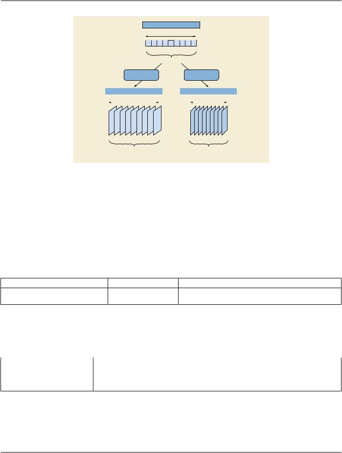
Figure TTT.2.3-1. Encoding of two 3D reconstructions of different regions of the anatomy​

TTT.2.3.3 Encoding Details​

TTT.2.3.3.1 X-Ray 3D Angiographic Image IOD​

TTT.2.3.3.1.1 Frame of Reference Module Recommendations​

Sincethetwovolumesarereconstructedfromthesameprojections,thereconstructionapplicationwillusethesamepatientcoordinate​ system on both volumes so that the spatial location of the object of interest in both volumes will be the same. Therefore the two X-​ Ray 3D Instances will have the same Frame of Reference (FoR) UID. If the originating 2D Instances do not deliver a value of FoR​ UID, a new FoR UID has to be created for the reconstructed volumes.​

Table TTT.2.3-1. Frame of Reference Module Recommendations​

Attribute Name​

Tag​

Recommendation​

Frame of Reference UID​

(0020,0052)​

Use the same value for the full field of view volume and the​


sub-region volume.​

TTT.2.3.3.1.2 Pixel Measures Macro Recommendations​

The detailed size of the volume element (Pixel Spacing for x/y dimension and Slice Thickness for z dimension) may be different​ between the full field of view reconstruction and the sub-region reconstruction.​

Table TTT.2.3-2. Pixel Measures Macro Recommendations​

Attribute Name​

Tag​

Recommendation​

Pixel Measures Sequence​

(0028,9110)​

Thepixelsizesand/orslicethicknessarenotnecessarilyequalinthetwo​


reconstructed volumes. Within each individual volume this sequence is​


encoded as "shared".​

TTT.2.3.3.1.3 Plane Position (Patient) Macro Recommendations​

The plane position of the first slice in the first volume may have a different value than in the second volume, as the sub-region volume​ can be smaller and shifted with respect to the full field of view volume.​

- Standard -​

Page 692​

DICOM PS3.17 2020a - Explanatory Information​

TTT.2.3.3.1.4 Plane Orientation (Patient) Macro Recommendations​

The plane orientation could be different in the second volume depending on the application needs, e.g., to align the slices with the​ object of interest.​

TTT.2.3.3.1.5 Frame Content Macro Recommendations​

This module encodes the timing information of the frames, as well as dimension and stack index values.​

Table TTT.2.3-3. Frame Content Macro Recommendations​

Attribute Name​

Tag​

Recommendation​

Frame Content Sequence​

(0020,9111)​

Provides details for each frame.​

>Frame Acquisition Duration​

(0018,9220)​

Use the duration of the rotational acquisition in the two​


reconstructed volumes.​

TTT.2.3.3.1.6 Frame Anatomy Macro Recommendations​

The volume directly reconstructed from a sub-region of each of the original projection X-Ray frames does not necessarily reflect the​ same anatomy or laterality as the full field of view volume. Therefore the Frame Anatomy macro may point to a different anatomic​ context than the one documented for the originating frames.​

TTT.2.3.4 Example​

In this example, the slices of the two volumes are reconstructed in the axial plane of the patient; the row direction is aligned in the​ positive x-direction of the patient (right-left) and the column direction is aligned in the positive y-direction of the patient (anterior-pos-​ terior).​

The full field of view reconstruction in encoded with the Instance UID "Z1" and consists of a 512 cube volume of 0.2 mm of voxel size.​ The sub-region reconstruction in encoded with the Instance UID "Z2" and consists of a 256 cube volume of the voxel size of 0.1 mm.​

Both volumes share the same Frame of Reference UID.​

SOP Instance UID

(0008,0018)


= UID “Z1”


Rows

(0028,0010)

= 512


Columns

(0028,0011)

= 512


...


Frame of Reference UID

(0020,0052)


= UID “D”


...


Shared Functional Group Sequence

(5200,9229)


Item 1


Common to all frames of the X-Ray 3D


...


>Pixel Measures Sequence

(0028,9110)


Item 1


>>Slice Thickness

(0018,0050)

= 0.2


>>Pixel Spacing

(0028,0030)

= 0.2


>Plane Orientation Sequence

(0028,9116)


Item 1


>>Image Orientation (Patient)

(0020,0037)

= 1\0\0\0\1\0


>Frame Anatomy Sequence

(0020,9071)


Item 1


>>Frame Laterality

(0020,9072)


provide value


>>Anatomic Region Sequence

(0008,2218)


provide anatomic region


...


...


Per-Frame Functional Groups Sequence

(5200,9230)


“M” frames


...


Frame “i” of the X-Ray 3D


Item i


>Plane Position Sequence

(0020,9113)


Item 1


>>Image Position (Patient)

(0020,0032)


...


Figure TTT.2.3-2. Attributes of 3D Reconstruction of the full field of view of the projection frames​

- Standard -​

DICOM PS3.17 2020a - Explanatory Information​

Page 693​

SOP Instance UID

(0008,0018)


= UID “Z2”


Rows

(0028,0010)

= 256


Columns

(0028,0011)

= 256


...


Frame of Reference UID

(0020,0052)


= UID “D”


...


Shared Functional Group Sequence

(5200,9229)


Item 1


Common to all frames of the X-Ray 3D


...


>Pixel Measures Sequence

(0028,9110)


Item 1


>>Slice Thickness

(0018,0050)

= 0.1


>>Pixel Spacing

(0028,0030)

= 0.1


>Plane Orientation Sequence

(0028,9116)


Item 1


>>Image Orientation (Patient)

(0020,0037)

= 1\0\0\0\1\0


>Frame Anatomy Sequence

(0020,9071)


Item 1


>>Frame Laterality

(0020,9072)


May be different value vs. full reconstruction


>>Anatomic Region Sequence

(0008,2218)


May be different value vs. full reconstruction


...


...


Per-Frame Functional Groups Sequence

(5200,9230)


“P” frames


...


Frame “i” of the X-Ray 3D


Item i


>Plane Position Sequence

(0020,9113)


Item 1


>>Image Position (Patient)

(0020,0032)


May be different value vs. full reconstruction


...


Figure TTT.2.3-3. Attributes of 3D Reconstruction using a sub-region of all frames​

TTT.2.4 Case #4: Multiple Rotations, One Or More 2D Instances, One Reconstruction, One X-​ Ray 3D Instance​

This application case is related to a high resolution reconstruction from several rotations around the same anatomy.​

TTT.2.4.1 User Scenario​

Theimageacquisitionsystemperformsmultiple2Drotationalacquisitionsaroundthepatientwithmovementsinthesameoropposite​ directions in the patient's transverse plane. A single volume is reconstructed from the acquired data (e.g., through "back-projection"​ algorithm). The reconstruction can either occur on the same system (e.g., Acquisition Modality) or a secondary processing system​ (e.g., Co-Workstation).​

The reconstructed Volume needs to be encoded and saved for further use.​

TTT.2.4.2 Encoding Outline​

The rotational acquisitions can be encoded either as a single instance (e.g., "C") containing several rotations or as several instances​ (e.g., "C1", "C2", etc.) containing one rotation per instance. The rotational acquisitions can either be encoded as XA Image(s) with​ limited frame-specific Attributes or as Enhanced XA Image(s), with frame-specific Attributes encoded that inform the algorithms to​ reconstruct a volume.​

The reconstructed volume data is encoded as a single X-Ray 3D Angiographic instance. The reconstructed region covers typically​ the full field of view of the projected matrix size.​

All frames of the original XA Images or Enhanced XA Images are used to reconstruct the volume.​

TheX-Ray3DinstancereferencestheoriginalacquisitioninstancesandrecordsAttributesoftheprojectionsdescribingtheacquisition​ context.​

- Standard -​

Page 694​

DICOM PS3.17 2020a - Explanatory Information​

XA 2D Projection SOP Instance “C”


Rotation #1


Rotation #2


Rotation #3


N1...


...N2 N3...


...N4 N5...


...N6

Acquisition Context #1 Acquisition Context #2 Acquisition Context #3

Reconstruction #1

X-Ray 3D SOP Instance “Z”

1...

...M

Reconstruction #1

- From Acquisition Context #1, #2, #3

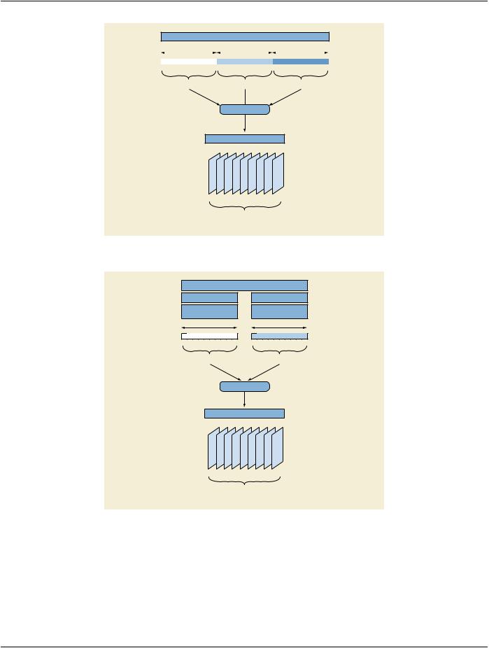
Figure TTT.2.4-1. Encoding of one 3D reconstruction from three rotational acquisitions in one instance​

Study “A”

Series “B1”

XA 2D Projection

SOP Instance “C1”

Rotation #1

Series “B2”

XA 2D Projection

SOP Instance “C2”

Rotation #2

1...

...N1

1...

...N2

Acquisition Context #1

Acquisition Context #2

Reconstruction #1

X-Ray 3D SOP Instance “Z”

1...

...M

Reconstruction #1

- From Acquisition Context #1, #2

Figure TTT.2.4-2. Encoding of one 3D reconstruction from two rotational acquisitions in two instances​

TTT.2.4.3 Encoding Details​

TTT.2.4.3.1 2D X-Ray Angiographic Image IOD​

This scenario is based on the encoding of the different rotations in one or more 2D instance(s), which can be encoded either as X-​ Ray Angiography or Enhanced XA Images.​

- Standard -​

DICOM PS3.17 2020a - Explanatory Information​

Page 695​

TTT.2.4.3.1.1 Frame of Reference Module Recommendations​

In the case of multiple source 2D Instances, the acquisition equipment assumes that the patient has not moved between the different​ rotations. This module encodes the same FoR UID in all the rotations, identifying a common spatial relationship between them, thus​ allowing the 3D reconstruction to use the projections of all the rotations to perform a single volume reconstruction.​

If the source 2D Instances do not provide a value of FoR UID, it has to be created for the reconstructed volume.​

Table TTT.2.4-1. Frame of Reference Module Recommendations​

Attribute Name​

Tag​

Recommendation​

Frame of Reference UID​

(0020,0052)​

All XA Images or Enhanced XA Images created from the rotational​


acquisitions share the same spatial relationship.​

Position Reference Indicator​

(0020,1040)​

No recommendation to set a value, unless a system is capable to derive​


such information from the anatomy or has a mandatory user interface to​


enter such information.​

Note​

The case where all the source 2D Instances have the same FoR UID is the "lucky" case. If no FoR UID value is provided in​ the 2D Instances, or if the FoR UIDs are different, there should be an additional 2D registration step before performing the​ 3D reconstruction.​

TTT.2.4.3.2 X-Ray 3D Angiographic Image IOD​

TTT.2.4.3.2.1 X-Ray 3D Angiographic Image Contributing Sources Module Recommendations​

This module encodes the source SOP instance(s) used to create the X-Ray 3D Angiographic instance.​

Table TTT.2.4-2. X-Ray 3D Angiographic Image Contributing Sources Module Recommendations​

Attribute Name​

Tag​

Recommendation​

Contributing Sources Sequence​

(0018,9506)​

One item for each of the originating instances that was used for the​


reconstruction of the X-Ray 3D Angiographic image.​

TTT.2.4.3.2.2 X-Ray 3D Angiographic Acquisition Module Recommendations​

There are multiple acquisition contexts, one per rotation of the equipment. This module encodes the frame numbers of the source​ SOP instance that belong to each acquisition context, as well as the important technical and physical parameters of the source SOP​ instances used to create the X-Ray 3D Angiographic instance.​

Table TTT.2.4-3. X-Ray 3D Angiographic Acquisition Module Recommendations​

Attribute Name​

Tag​

Recommendation​

X-Ray 3D Acquisition Sequence​

(0018,9507)​

One item for each acquisition context (i.e., each rotation) that​


contributed to the reconstruction of the X-Ray 3D Angiographic​


image pixel data contents.​

…​


>Source Image Sequence​

(0008,2112)​

One item for each acquisition context.​

>>Referenced SOP Class UID​

(0008,1150)​


>>Referenced SOP Instance UID​

(0008,1155)​

The source SOP instance where this rotation belongs.​

>>Referenced Frame Number​

(0008,1160)​

The frame numbers of the projections corresponding to this​


rotation.​

…​

- Standard -​

Источник: https://studfile.net/preview/14585770/