Материал: part17

Внимание! Если размещение файла нарушает Ваши авторские права, то обязательно сообщите нам

DICOM PS3.17 2020a - Explanatory Information​

Page 701​

TTT.2.5.4 Example​

In this example the gantry performs one single rotation around the heart at 20 degrees per second, covering an arc of 200 degrees​ during 10 seconds. Approximately 10 cardiac cycles are acquired. The frame rate is 8 frames per second, resulting in 8 projections​ acquired at each cardiac cycle corresponding to 8 different cardiac phases.​

Overall there will be 80 projections; 10 projections for each of the 8 cardiac phases. Each cardiac phase represents one acquisition​ context.Theinformationofthecardiactriggerdelaytimeisencodedforeachprojection.TheprojectionsareencodedasanXAImage​ with the Instance UID "C".​

The reconstruction application creates 8 volumes, each volume is reconstructed by a back-projection from the 10 frames having the​ same cardiac trigger delay time, i.e., the frames acquired at the same cardiac phase. Each volume contains 256 frames. The 8 recon-​ structed volumes are encoded in one single X-Ray 3D Angiographic instance of Instance UID "Z".​

SOP Instance UID

(0008,0018)

=UID “Z”


...


X-Ray 3D Acquisition Sequence

(0018,9507)


Acquisition context #1


Item 1


>Source Image Sequence

(0008,2112)


Item 1


>>Referenced SOP Class UID

(0008,1150)

= XA Image or Enhanced XA Image


>>Referenced SOP Instance UID

(0008,1155)

= UID “C”


>>Referenced Frame Number

(0008,1160)

= 1\9\17\25...


>... (other attributes of this source)


Acquisition context #2


Item 2


>Source Image Sequence

(0008,2112)


Item 1


>>Referenced SOP Class UID

(0008,1150)

= XA Image or Enhanced XA Image


>>Referenced SOP Instance UID

(0008,1155)

= UID “C”


>>Referenced Frame Number

(0008,1160)

= 2\10\18\26...


>... (other attributes of this source)


...


...


X-Ray 3D Reconstruction Sequence

(0018,9530)


Reconstruction #1


Item 1


>Acquisition Index

(0020,9518)

= 1


= Cardiac Phase A


>Reconstruction Description

(0020,9518)


>... (other attributes related to this reconstruction)


Reconstruction #2


Item 2


>Acquisition Index

(0020,9518)

= 2


= Cardiac Phase B


>Reconstruction Description

(0020,9518)


>... (other attributes related to this reconstruction)


...


...


Dimension Organization Sequence

(0020,9221)


One dimension


Item 1


>Dimension Organization UID

(0020,9164)

= UID “E”


Dimension Index Sequence

(0020,9222)


Item 1


>Dimension Organization UID

(0020,9164)

= UID “E”


>Dimension Index Pointer

(0020,9165)

= (0020,9241)


>Functional Group Pointer

(0020,9167)

= (0018,9118)


Item 1


>Dimension Organization UID

(0020,9164)

= UID “E”


>Dimension Index Pointer

(0020,9165)

= (0020,0032)


>Functional Group Pointer

(0020,9167)

= (0020,9113)

Dimension Organization Type

(0020,9311)

= 3D

...


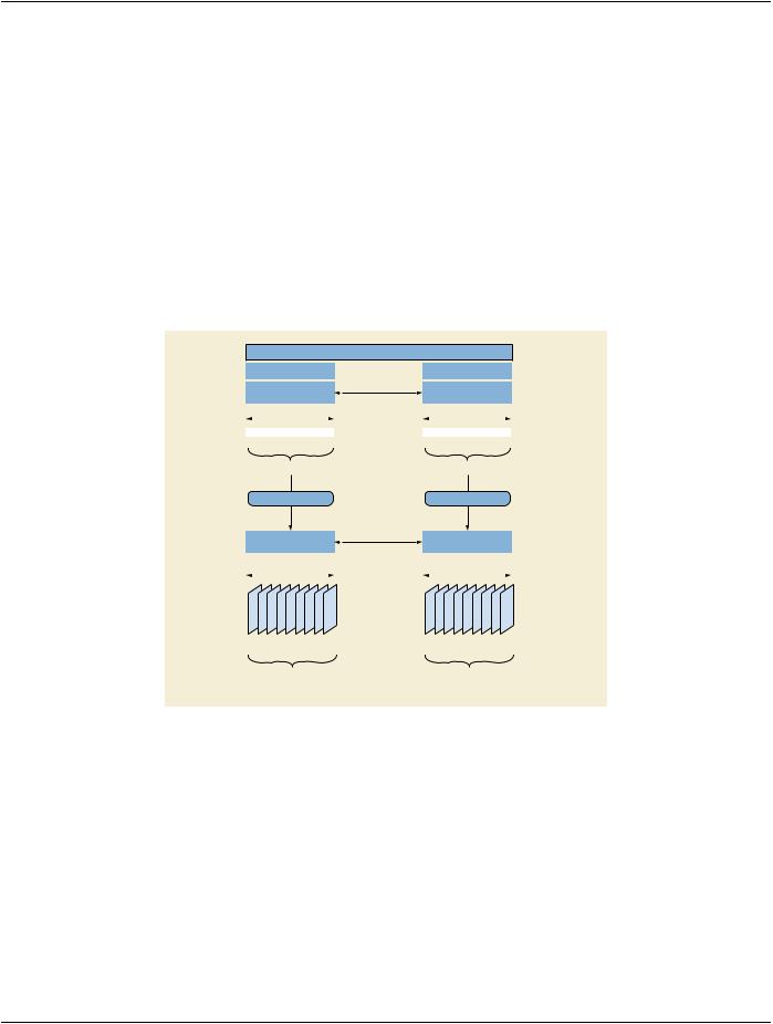
Figure TTT.2.5-2. Common Attributes of 3D Reconstruction of Three Cardiac Phases​

- Standard -​

Page 702​


DICOM PS3.17 2020a - Explanatory Information​


...


Per-Frame Functional Groups Sequence


Item 1


Frame “1” of the X-Ray 3D


>X-Ray 3D Frame Type Sequence

(0018,9504)


Item 1


>>Reconstruction Index

(0020,9536)

= 1


>Frame Content Sequence

(0020,9111)


Item 1


>>Frame Reference DateTime

(0018,9151)


= 1st frame of source of cardiac phase A


>>Frame Acquisition DateTime

(0018,9074)


= 1st frame of source of cardiac phase A


>>Cardiac Cycle Position

(0018,9236)


= END_SYSTOLE


>>Dimension Index Values

(0020,9157)

= 1\1


>>Stack ID

(0020,9056)

= 1


>>In-Stack Position Number

(0020,9057)

= 1


>Cardiac Synchronization Sequence

(0018,9118)


Item 1


>>Nominal Percentage of Cardiac Phase

(0020,9241)

= 0.0


>>Nominal Cardiac Trigger Delay Time

(0020,9153)

= 0.0


...


Item 2


Frame “2” of the X-Ray 3D


>X-Ray 3D Frame Type Sequence

(0018,9504)


Item 1


>>Reconstruction Index

(0020,9536)

= 1


>Frame Content Sequence

(0020,9111)


Item 1


>>Frame Reference DateTime

(0018,9151)


= 1st frame of source of cardiac phase A


>>Frame Acquisition DateTime

(0018,9074)


= 1st frame of source of cardiac phase A


>>Cardiac Cycle Position

(0018,9236)


= END_SYSTOLE


>>Dimension Index Values

(0020,9157)

= 1\2


>>Stack ID

(0020,9056)

= 1


>>In-Stack Position Number

(0020,9057)

= 2


>Cardiac Synchronization Sequence

(0018,9118)


Item 1


>>Nominal Percentage of Cardiac Phase

(0020,9241)

= 0.0


>>Nominal Cardiac Trigger Delay Time

(0020,9153)

= 0.0


...


Item 257


Frame “257” of the X-Ray 3D


>X-Ray 3D Frame Type Sequence

(0018,9504)


Item 1


>>Reconstruction Index

(0020,9536)

= 2


>Frame Content Sequence

(0020,9111)


Item 1


>>Frame Reference DateTime

(0018,9151)


= 1st frame of source of cardiac phase B


>>Frame Acquisition DateTime

(0018,9074)


= 1st frame of source of cardiac phase B


>>Cardiac Cycle Position

(0018,9236)


= UNDETERMINED


>>Dimension Index Values

(0020,9157)

= 2\1


>>Stack ID

(0020,9056)

= 1


>>In-Stack Position Number

(0020,9057)

= 1


>Cardiac Synchronization Sequence

(0018,9118)


Item 1


>>Nominal Percentage of Cardiac Phase

(0020,9241)

= 12.5


>>Nominal Cardiac Trigger Delay Time

(0020,9153)

= 0.125


...


Figure TTT.2.5-3. Per-Frame Attributes of 3D Reconstruction of Three Cardiac Phases​

TTT.2.6 Case #6: Two Rotations, Two 2D Instances, Two Reconstructions, Two X-Ray 3D In-​ stances​

This application case is related to two rotational acquisitions on the same anatomical region before and after the intervention, with​ table movement between the two acquisitions. The two reconstructed volumes are created and automatically registered on the same​ patient coordinate system.​

TTT.2.6.1 User Scenario​

The image acquisition system performs two different 2D rotational acquisitions at two different times of the interventional procedure:​ the first acquisition before the intervention (e.g., before placement of a stent) and the second one after the intervention.​

- Standard -​

DICOM PS3.17 2020a - Explanatory Information​

Page 703​

Between the two acquisitions the table position has changed with respect to the Isocenter. The rotational acquisitions are performed​ with the same spatial trajectory of the X-Ray Detector relative to the Isocenter; therefore the second acquisition contains a slightly​ different region of the patient.​

Two 3D volumes are reconstructed, one for each rotational acquisition. After the intervention, the two 3D volumes are displayed to-​ gether on the same patient coordinate system. The user can visually assess the placement of the stent over the anatomy pre-inter-​ vention. The patient position on the table does not change during the procedure.​

TTT.2.6.2 Encoding Outline​

The rotational acquisitions can either be encoded as XA Image or as Enhanced XA Image. The two XA instances (let's call them "C1"​ and "C2") are encoded in two different Series ("B1" and "B2") of the same Study ("A").​

The volume data is encoded as two X-Ray 3D Angiographic instances ("Z1" and "Z2"). The volumes are typically a full set (in number​ of rows, columns and slices) of the projected matrix size (in number of rows and columns).​

Each reconstructed volume contains one acquisition context consisting of all the frames of the corresponding source 2D XA Image.​ To display the two volumes together, they share the same Frame of Reference UID.​

Study “A”


Series “B1”


Series “B2”


Same Frame of


XA 2D Projection


XA 2D Projection


SOP Instance “C1”

Reference


SOP Instance “C2”


Pre-intervention


Post-intervention


1...


...N1


1...


...N2

Acquisition Context C1 #1


Acquisition Context C2 #1


Reconstruction Z1 #1


Reconstruction Z2 #1


Same Frame of


X-Ray 3D


X-Ray 3D


SOP Instance “Z1”

Reference


SOP Instance “Z2”


3D pre-intervention


3D post-intervention


1... ...M1 1... ...M2

Reconstruction Z1 #1

Reconstruction Z2 #1

- From Acquisition Context C1 #1

- From Acquisition Context C2 #1

Figure TTT.2.6-1. Encoding of two 3D reconstructions at different steps of the intervention​

TTT.2.6.3 Encoding Details​

TTT.2.6.3.1 X-Ray 3D Angiographic Image IOD​

TTT.2.6.3.1.1 Frame of Reference Module Recommendations​

Since the purpose of this scenario is to overlap the two volumes without additional spatial registration, the spatial location of the​ anatomyofinterestinbothvolumesneedstobethesame.Tokeepthetwovolumesspatiallyregistered,thereconstructionapplication​ will use the table position of both rotations to correct the table movement with respect to the Isocenter, thus creating both volumes​ with the same spatial origin and axis, i.e., same patient coordinate system.​

Therefore, it is recommended to encode both instances with the same FoR UID, equal to the Frame of Reference UID of the XA​ projection images. If the originating XA images do not contain a Frame of Reference UID, the reconstruction application will create​ the FoR UID equal for the two reconstructed volumes.​

- Standard -​

Page 704​ DICOM PS3.17 2020a - Explanatory Information​

Table TTT.2.6-1. Frame of Reference Module Recommendations​

Attribute Name​

Tag​

Recommendation​

Frame of Reference UID​

(0020,0052)​

Use the same FoR UID value for both volumes.​

Position Reference Indicator​

(0020,1040)​

Use a value either provided by the operator of the acquisition​


modality or the reconstruction console, if supplied.​

TTT.2.6.3.1.2 Patient Orientation Module Recommendations​

This module encodes the patient orientation with respect to the table. It is supposed to contain the same values in both 3D volumes,​ since the patient does not move between the two rotational acquisitions.​

TTT.2.6.3.1.3 Pixel Measures Macro Recommendations​

The detailed size of the volume element (Pixel Spacing for row/column dimension of each slice and Slice Thickness for the distance​ ofslices)dependsonthereconstructionalgorithmandisnotnecessarilyidenticaltotherelatedsizesinthesource(projection)image(s).​

Table TTT.2.6-2. Pixel Measures Macro Recommendations​

Attribute Name​

Tag​

Recommendation​

Pixel Measures Sequence​

(0028,9110)​

Provide it as a shared macro, i.e., each slice of a volume has​


the same Pixel Spacing and Slice Thickness.​

>Pixel Spacing​

(0028,0030)​

May be different between the two volumes.​

>Slice Thickness​

(0018,0050)​

May be different between the two volumes.​

TTT.2.6.3.1.4 Plane Position (Patient) Macro Recommendations​

This macro encodes the position of the 3D slices relative to the patient.​

It is assumed that the patient does not move on the table between the two rotational acquisitions, but the table moves with respect​ to the Isocenter. Although the spatial trajectory of the X-Ray Detector relative to the Isocenter of the two rotational acquisitions is the​ same, the two volumes contain a different region of the patient.​

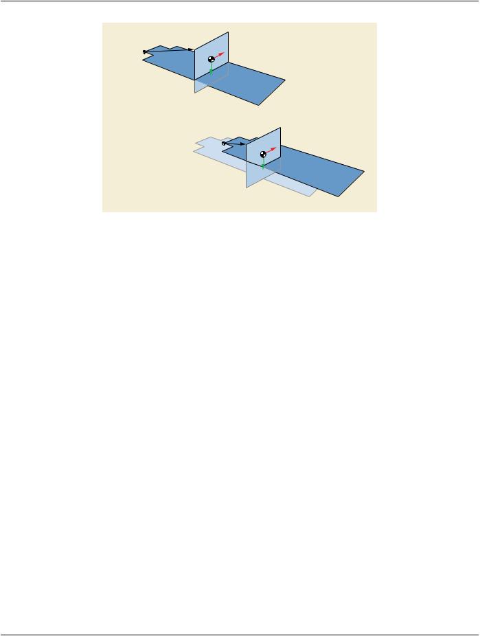
To allow spatial registration between the two volumes, the position of the slices of the two volumes need to be defined with respect​ to the same point of the patient. As the patient does not move on the table, the reconstruction application will define the patient origin​ as a fixed point on the table, so that the 3D slices of the two volumes are all related to the same fixed point on the table (i.e., same​ point of the patient) by the Attribute Image Position (Patient) (0020,0032).​

- Standard -​

DICOM PS3.17 2020a - Explanatory Information​

Page 705​

Table


Fixed Point

Isocenter


X-Ray

Table

3D pre-intervention

Table

Fixed Point

Isocenter

X-Ray

Table

3D post-intervention

Figure TTT.2.6-2. One frame of two 3D reconstructions at two different table positions​

The volume is positioned in the spatial coordinates identified by the frame of reference, which is common to the two volumes.​ Therefore, the position of the slices of both volumes is defined with respect to the same patient origin.​

TTT.2.6.3.1.5 Plane Orientation (Patient) Macro Recommendations​

The slices can be oriented in any relation wrt. the patient coordinate system. The plane orientation is expected to be the same for the​ two volumes; however it could be different without compromising the registration.​

TTT.2.6.4 Example​

In this example, two rotational images are acquired; the first one before the intervention and the second one after the intervention.​ They are encoded with the Instance UIDs "C1" and "C2" respectively.​

In both rotational acquisitions, the patient position with respect to the table is head-first prone, and the table is not rotated nor tilted​ with respect to the Isocenter. The patient coordinates and the Isocenter coordinates are then aligned on x, y and z.​

The patient origin is defined by the application as a fixed point on the table.​

During the first rotational acquisition, the table position with respect to the Isocenter in the lateral direction [x] is +20mm, in the vertical​ direction [y] is +40mm, and in the longitudinal direction [z] is +60mm.​

During the second rotational acquisition, the table position with respect to the Isocenter in the lateral direction [x] is -10mm, in the​ vertical direction [y] is +80mm, and in the longitudinal direction [z] is +110mm.​

Thesecondacquisitionisperformedwitharelativetablemovementof(-30,40,50)mmvs.thefirstacquisitioninthepatientcoordinates​ system. Therefore, for a given 3D slice "i" of the two volumes, the Image Position (Patient) (0020,0032) of the second volume is​ translated of (+30,-40,-50) mm vs. the Image Position (Patient) (0020,0032) of the first volume.​

The two reconstructions are performed with the same number of rows, columns and slices, and both at the same resolution of 0.2​ mm/voxel.Notethatiftheresolutionwasdifferent,theImagePosition(Patient)(0020,0032)ofthesecondvolumewouldbeadditionally​ translated by the shift of the TLHC pixels relative to the center of the volume, because both volumes are centered at the Isocenter.​

The reconstructions are encoded in two X-Ray 3D Angiographic instances of Instance UIDs "Z1" and "Z2" respectively.​

- Standard -​

Источник: https://studfile.net/preview/14585770/