Page 710 |
DICOM PS3.17 2020a - Explanatory Information |
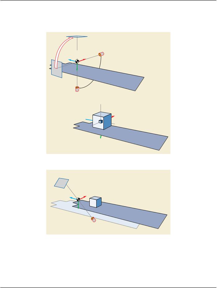
table has moved between the acquisitions. See Section C.8.19.6.13.1 “Isocenter Reference System Attribute Description” in PS3.3 for further explanation about the projection on the image plane of a point defined in the table coordinate system.
TTT.2.7.4 Example
In this example, one rotational image is acquired before the intervention. It is encoded with the Instance UID "C1". Then a second projection static image is acquired during the intervention. It is encoded with the Instance UID "C2". Both acquisitions are encoded as Enhanced XA SOP Class.
In both acquisitions, the patient position with respect to the table is head-first prone, and the table is not rotated nor tilted with respect to the Isocenter. Therefore, the axis of the patient coordinate system and the Isocenter coordinate system are aligned, and the 3x3 matrix Mij of the Image to Equipment Mapping Matrix (0028,9520) is the identity.
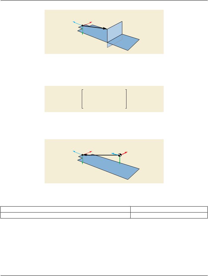
In this example, the patient origin is defined by the application as a fixed point on the table; when the table position is zero, the patient origin is the point (0,0,200) in the Isocenter coordinates system (in mm).
During the rotational acquisition, the table position with respect to the Isocenter in the lateral direction [x] is +20mm, in the vertical direction [y] is +40mm, and in the longitudinal direction [z] is +60mm. Therefore, the terms (Tx,Ty,Tz) of the Image to Equipment Mapping Matrix (0028,9520) are (20,40,260).
During the second acquisition, the table position with respect to the Isocenter in the lateral direction [x] is +40mm, in the vertical dir- ection [y] is +30mm, and in the longitudinal direction [z] is +20mm.
Consequently, the second acquisition is performed with a relative table translation of (30,-10,-50) mm vs. the first acquisition in the Isocentercoordinatesystem.Thepositionerprimaryangleis-30deg.(RAO)andthesecondaryangleis20deg.(CRA).Thedistances from the source to the Isocenter and from the source to the detector are 780 mm and 1200 mm respectively.
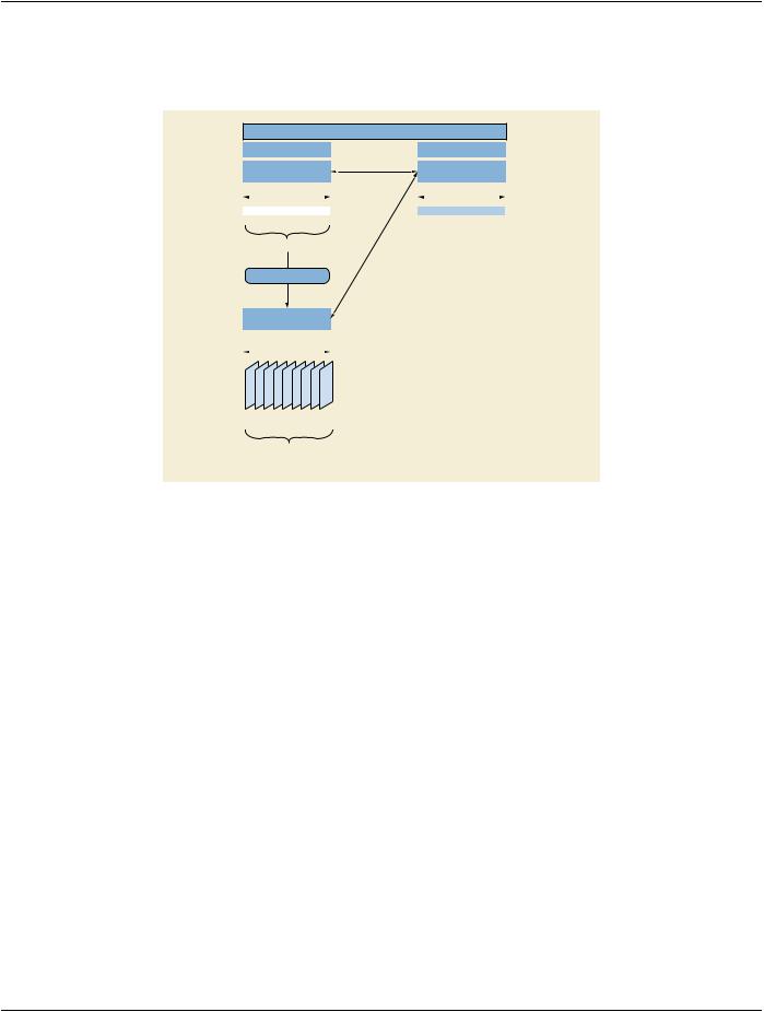
The reconstruction is encoded in an X-Ray 3D Angiographic instance of Instance UID "Z1".
SOP Instance UID |
(0008,0018) |
= UID “Z1” |
|
|
|
|
|
|
|
|
|
|
|
... |
|
|
|
|
|
|
|
|
|
|
|
|
|
|
|
|
|
|
|
|
|
Frame of Reference UID |
(0020,0052) |
= UID “D” |
|
|
|
|
|
|
|
|
|
|
|
... |
|
|
|
|
|
|
|
|
|
|
|
|
|
Image to Equipment Mapping Matrix |
(0028,9520) |
= 1\0\0\20\0\1\0\40\0\0\1\260\0\0\0\1 |
|
|
|
|
= ISOCENTER |
Equipment Coordinate System Identification |
(0028,9537) |
|
|
|
|
|
|
|
|
|
|
|
... |
|
|
|
|
|
|
|
|
|
|
|
|
|
|
|
|
|
|
|
|
|
Contributing Sources Sequence |
(0018,9506) |
|
|
|
|
|
|
|
|
|
|
|
|
|
Item 1 |
|
|
|
|
>Contributing SOP Instances Reference Sequence |
(0020,9529) |
|
|
|
|
|
|
|
|
|
|
|
|
|
|
|
Item 1 |
|
|
|
|
|
|
>>Reference Series Sequence |
(0008,1115) |
|
|
|
|
|
|
Item 1 |
|
|
|
|
|
|
|
|
|
|
|
|
|
|
|
|
|
|
|
>>>Referenced Instance Sequence |
(0008,114a) |
|
|
|
|
|
|
|
|
|
|
|
|
|
|
|
|
|
|
|
Item 1 |
|
|
|
|
|
|
|
|
|
|
>>>>Referenced SOP Class UID |
(0008,1150) |
= XA Image or Enhanced XA Image |
|
|
|
|
|
|
|
|
|
|
|
|
|
|
|
|
|
|
|
>>>>Referenced SOP Instance UID |
(0008,1155) |
= UID “C1” |
|
|
|
|
|
|
|
|
|
|
|
|
|
|
|
|
|
>>>Series Instance UID |
(0020,000e) |
= UID “B1” |
|
|
|
|
|
|
|
|
|
|
|
|
|
|
|
>>Study Instance UID |
(0020,000d) |
= UID “A” |
|
|
|
|
|
|
|
|
|
|
|
|
|
>... (other attributes from the contributing image sources) |
|
|
|
|
|
|
|
|
|
|
|
|
|
... |
|
|
|
|
|
|
|
|
|
|
|
|
|
X-Ray 3D Acquisition Sequence |
(0018,9507) |
|
|
|
|
Acquisition context #1 |
|
Item 1 |
|
|
|
>Source Image Sequence |
(0008,2112) |
|
|
|
|
|
|
|
|
|
|
Item 1 |
|
|
|
|
|
|
>>Referenced SOP Class UID |
(0008,1150) |
= Enhanced XA Image |
|
|
|
|
>>Referenced SOP Instance UID |
(0008,1155) |
= UID “C1” |
|
|
>Table X Position to Isocenter |
(0018,9466) |
= 20.0 |
|
|
>Table Y Position to Isocenter |
(0018,9467) |
= 40.0 |
|
|
>Table Z Position to Isocenter |
(0018,9468) |
= 60.0 |
|
|
|
|
|
|
|
>Table Horizontal Rotation Angle |
(0018,9469) |
= 0.0 |
|
|
|
|
|
|
|
>Table Head Tilt Angle |
(0018,9470) |
= 0.0 |
|
|
|
|
|
|
|
>Table Cradle Tilt Angle |
(0018,9471) |
= 0.0 |
|
|
>... (other attributes of this acquisition context) |
|
|
|
|
|
|
|
|
|
|
|
|
|
Figure TTT.2.7-7. Attributes of the pre-intervention 3D reconstruction