Материал: The_Future_of_Hydrogen-IEA-2020

The Future of Hydrogen |
Chapter 2: Producing hydrogen and hydrogen-based products |
|
|
|
|
Box 3. Emerging technologies to produce hydrogen
Methane splitting offers a potential new way to produce hydrogen from natural gas. Various technologies have been developed since the 1990s. The main technology is based on alternatingcurrent three-phase plasma, and uses methane as a feedstock and electricity as an energy source. It produces hydrogen and solid carbon, but no CO2 emissions (Fulcheri, 2018).
Methane splitting requires high-temperature plasma and significant thermal losses reduce its efficiency advantage, but it uses three to five times less electricity than electrolysis for the same amount of hydrogen produced. It has very low CO2 formation and creates solid carbon in the form of carbon black. It requires more natural gas than electrolysis, but could create additional revenue streams from the sale of carbon black for use in rubber, tyres, printers and plastics. The US firm Monolith Materials operates a pilot methane splitting plant in California and is building an industrial plant in Nebraska; the Nebraska plant will ultimately be run on low-carbon electricity and sell hydrogen to the Nebraska Public Power District, which plans to convert a 125 MW coal plant to burn hydrogen instead of coal. Although the total efficiency would be lower than using the natural gas directly in the power plant, the emissions from gas combustion would be avoided and the hydrogen would effectively be a “store” of input electricity for the power network.
Global demand for carbon black is expected to increase from 12 Mt to 16 Mt in the next five years, which would have significant accompanying CO2 emissions using current technology. Producing under 5 MtH2/yr of hydrogen via methane splitting could substitute all this demand and avoid these emissions. Markets for other exotic forms of solid carbon – carbon nanotubes, carbon fibres, graphene – are one to two orders of magnitude smaller than that for carbon black, but could grow rapidly with the expansion of batteries or carbon-reinforced concrete (Dagle et al., 2017). Other solid carbon markets may provide other options (Hanson, 2018).
Meanwhile, alternative process designs for SMR are being explored. While natural gas would still be required as feedstock, other energy sources could be used to produce the necessary steam, and this could facilitate the capture of the more concentrated “process” CO2 stream. Electricity is a potential candidate for the production of the necessary high-temperature steam (Bazzanella and Ausfelder, 2017), while concentrating solar heat could be used in areas with the right kind of solar resources.
If even higher levels of solar concentration could generate temperatures of around 800–1 000°C, solar energy could be used directly to split water into hydrogen and oxygen without the need for natural gas and CO2 storage. The technology for these higher solar concentration levels, however, is still at laboratory scale.
Sources: Fulcheri (2018), “Direct decarbonization of methane by thermal plasma for the co-production of hydrogen and carbon nanostructures”; Dagle et al. (2017), “An overview of natural gas conversion technologies for co-production of hydrogen and valueadded solid carbon products”; Bazzanella and Ausfelder (2017), “Low carbon energy and feedstock for the European chemical industry”; and personal communication with Rob Hanson, 2018.
PAGE | 41
IEA. All rights reserved.
The Future of Hydrogen |
Chapter 2: Producing hydrogen and hydrogen-based products |
Costs of hydrogen production from natural gas
The production cost of hydrogen from natural gas is influenced by various technical and economic factors, with gas prices and capital expenditure (CAPEX) being the two most important.
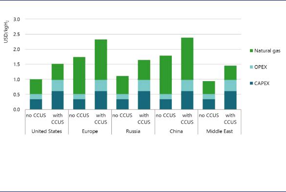
Fuel costs are the largest cost component in all regions and account for between 45% and 75% of production costs (Figure 9). Low gas prices in the Middle East, the Russian Federation, and North America give rise to some of the lowest hydrogen production costs. Gas importers such as Japan, Korea, China and India have to contend with higher gas import prices, and that makes for higher hydrogen production costs.
Figure 9. Hydrogen production costs using natural gas in different regions, 2018
Notes: kgH2 = kilogram of hydrogen; OPEX = operational expenditure. CAPEX in 2018: SMR without CCUS = USD 500–900 per kilowatt hydrogen (kWH2), SMR with CCUS = USD 900–1 600/kWH2, with ranges due to regional differences. Gas price = USD 3–11 per million British thermal units (MBtu) depending on the region. More information on the underlying assumptions is available at www.iea.org/hydrogen2019.
Source: IEA 2019. All rights reserved.
Availability of low-cost gas is a crucial cost determinant for SMR-based hydrogen.
Adding CCUS to SMR plants leads, on average, to cost increases of some 50% for CAPEX and some 10% for fuel, with the exact amounts depending on the design. It also leads on average to a doubling of OPEX as a result of CO2 transport and storage costs. In the most promising regions, however, costs for hydrogen from SMR with CCUS are in the range of USD 1.4–1.5/kgH2, making it one of the lowest cost low-carbon hydrogen production routes (see section “Comparison between alternative hydrogen production pathways” in this chapter.for a comparison with other production technologies).
Hydrogen from water and electricity
Water electrolysis is an electrochemical process that splits water into hydrogen and oxygen. Less than 0.1% of dedicated hydrogen production globally comes from water electrolysis today, and the hydrogen produced by this means is mostly used in markets where high-purity hydrogen is necessary (for example, electronics and polysilicon). In addition to the hydrogen
PAGE | 42
IEA. All rights reserved.

The Future of Hydrogen |
Chapter 2: Producing hydrogen and hydrogen-based products |
produced through water electrolysis, around 2% of total global hydrogen is created as a byproduct of chlor-alkali electrolysis in the production of chlorine and caustic soda.
With declining costs for renewable electricity, in particular from solar PV and wind, interest is growing in electrolytic hydrogen (Chapter 4) and there have been several demonstration projects in recent years. The efficiency of electrolyser systems today ranges between 60% and 81% depending on the technology type and load factor. Producing all of today’s dedicated
hydrogen output (69 MtH2) |
from |
electricity |
would |
result |
in an electricity demand of |
3 600 terawatt hours (TWh), |
more |
than the |
total |
annual |
electricity generation of the |
European Union. |
|
|
|
|
|
Electrolysis requires water as well as electricity. Around 9 litres of water are needed to produce 1 kgH2,9 producing 8 kilograms (kg) of oxygen as a by-product, which at smaller scale can be used in the health care sector or at a larger scale for industrial purposes. If all of today’s dedicated hydrogen production of around 70 MtH2 were to be produced by electrolysis, this would result in a water demand of 617 million cubic metres (m3), which would correspond to 1.3% of the water consumption of the global energy sector today (IEA, 2016) or roughly twice the current water consumption for hydrogen from SMR (345 million m3 of water for 52 MtH2 from SMR).
Freshwater access can be an issue in water-stressed areas. Using seawater could become an alternative in coastal areas. Using reverse osmosis for desalination requires an electricity demand of 3–4 kilowatt hours (kWh) per m3 of water and costs around USD 0.7–2.5 per m3 of water (Tractebel, 2018; Caldera et al., 2018). This has only a minor impact on the total costs of water electrolysis, increasing total hydrogen production costs by USD 0.01–0.02/kgH2. Direct use of seawater in electrolysis currently leads to corrosive damage and to the production of chlorine, but research is looking at how to make it easier to use seawater in electrolysis in the future.
Technology options
Three main electrolyser technologies exist today: alkaline electrolysis, proton exchange membrane (PEM) electrolysis, and solid oxide electrolysis cells (SOECs). Their main technical and economic characteristics are summarised in Table 3.
Alkaline electrolysis is a mature and commercial technology. It has been used since the 1920s, in particular for hydrogen production in the fertiliser and chlorine industries. The operating range of alkaline electrolysers goes from a minimum load of 10% to full design capacity. Several alkaline electrolysers with a capacity of up to 165 megawatts electrical (MWe) were built in the last century in countries with large hydropower resources (Canada, Egypt, India, Norway and Zimbabwe), although almost all of them were decommissioned when natural gas and steam methane reforming for hydrogen production took off in the 1970s. Alkaline electrolysis is characterised by relatively low capital costs compared to other electrolyser technologies due to the avoidance of precious materials.
PEM electrolyser systems were first introduced in the 1960s by General Electric to overcome some of the operational drawbacks of alkaline electrolysers. They use pure water as an electrolyte solution, and so avoid the recovery and recycling of the potassium hydroxide electrolyte solution that is necessary with alkaline electrolysers. They are relatively small,
9 For comparison, SMR without CCUS requires around 7 litres of raw water per kgH2 (IEAGHG, 2017b).
PAGE | 43
IEA. All rights reserved.

The Future of Hydrogen |
Chapter 2: Producing hydrogen and hydrogen-based products |
making them potentially more attractive than alkaline electrolysers in dense urban areas. They are able to produce highly compressed hydrogen for decentralised production and storage at refuelling stations (30–60 bar without an additional compressor and up to 100–200 bar in some systems, compared to 1–30 bar for alkaline electrolysers) and offer flexible operation, including the capability to provide frequency reserve and other grid services. Their operating range can go from zero load to 160% of design capacity (so it is possible to overload the electrolyser for some time, if the plant and power electronics have been designed accordingly). Against this, however, they need expensive electrode catalysts (platinum, iridium) and membrane materials, and their lifetime is currently shorter than that of alkaline electrolysers. Their overall costs are currently higher than those of alkaline electrolysers, and they are less widely deployed.
SOECs are the least developed electrolysis technology. They have not yet been commercialised, although individual companies are now aiming to bring them to market. SOECs use ceramics as the electrolyte and have low material costs. They operate at high temperatures and with a high degree of electrical efficiency. Because they use steam for electrolysis, they need a heat source. If the hydrogen produced were to be used for the production of synthetic hydrocarbons (power-to-liquid and power-to-gas), the waste heat from these synthesis processes (e.g. Fischer-Tropsch synthesis, methanation) could be recovered to produce steam for further SOEC electrolysis. Nuclear power plants, solar thermal or geothermal heat systems could also be heat sources for high-temperature electrolysis (Box 4).
Unlike alkaline and PEM electrolysers, it is possible to operate an SOEC electrolyser in reverse mode as a fuel cell, converting hydrogen back into electricity, which means it could provide balancing services to the grid in combination with hydrogen storage facilities. This would increase the overall utilisation rate of the equipment. It is also possible to use a SOEC electrolyser for co-electrolysis of steam and carbon dioxide, producing a gas mixture (carbon monoxide and hydrogen) for subsequent conversion to a synthetic fuel. One key challenge for those developing SOEC electrolysers is addressing the degradation of materials that results from the high operating temperatures.
Table 3. Techno-economic characteristics of different electrolyser technologies
|
|
|
|
Alkaline electrolyser |
PEM electrolyser |
|
|
SOEC electrolyser |
|||||||||||||||||||||
|
|
|
|
|
|
|
|
|
|
|
|
|
|
|
|
|
|
|
|
|
|
|
|
|
|
|
|
|
|
|
|
|
|
Today |
|
2030 |
|
Long |
|
Today |
|
2030 |
|
|
|
Long- |
|
|
|
Today |
|
|
|
2030 |
|
|
|
Long |
|
|
|
|
|
|
|
term |
|
|
|
|
|
term |
|
|
|
|
|
|
|
|
|
term |
|
||||||
|
|
|
|
|
|
|
|
|
|
|
|
|
|
|
|
|
|
|
|
|
|
|
|
|
|
|
|||
|
Electrical |
|
|
|
|
|
|
|
|
|
|
|
|
|
|
|
|
|
|
|
|
|
|
|
|
|
|
|
|
|
efficiency (%, |
|
63–70 |
65–71 |
70–80 |
56–60 |
63–68 |
|
|
67–74 |
|
|
74–81 |
|
|
77–84 |
|
|
77–90 |
||||||||||
|
LHV) |
|
|
|
|
|
|
|
|
|
|
|
|
|
|
|
|
|
|
|
|
|
|
|
|
|
|
|
|
|
|
|
|
|
|
|
|
|
|
|
|
|
|
|
|
|
|
|
|
|
|
|
|
|
|
|
|
|
|
|
Operating |
|
|
1–30 |
|
|
|
|
|
30–80 |
|
|
|
|
|
|
|
|
|
1 |
|
|
|
|
|
|
|
|
|
|
pressure (bar) |
|
|
|
|
|
|
|
|
|
|
|
|
|
|
|
|
|
|
|
|
|
|
|
|
|
|||
|
|
|
|
|
|
|
|
|
|
|
|
|
|
|
|
|
|
|
|
|
|
|
|
|
|
|
|
|
|
|
|
|
|
|
|
|
|
|
|
|
|
|
|
|
|
|
|
|
|
|
|
|
|
|
|
|
|
|
|
|
Operating |
|
|
|
|
|
|
|
|
|
|
|
|
|
|
|
650 |
|
|
|
|
|
|
|
|
|
|||
|
temperature |
|
60–80 |
|
|
|
|
50–80 |
|
|
|
|
|
|
|
|
– |
|
|
|
|
|
|
|
|
||||
|
(°C) |
|
|
|
|
|
|
|
|
|
|
|
|
|
|
|
1 000 |
|
|
|
|
|
|
|
|
|
|||
|
|
|
|
|
|
|
|
|
|
|
|
|
|
|
|
|
|
|
|
|
|||||||||
|
Stack lifetime |
|
|
60 000 |
|
90 000 |
|
100 000 |
|
30 000 |
|
60 000 |
|
|
|
100 000 |
|
|
|
10 000 |
|
|
|
40 000 |
|
|
|
75 000 |
|
|
(operating |
|
|
– |
|
– |
|
– |
|
– |
|
– |
|
|
|
– |
|
|
|
– |
|
|
|
– |
|
|
|
– |
|
|
hours) |
|
|
90 000 |
|
100 000 |
|
150 000 |
|
90 000 |
|
90 000 |
|
|
|
150 000 |
|
|
|
30 000 |
|
|
|
60 000 |
|
|
|
100 00 |
|
|
Load range |
|
|
|
|
|
|
|
|
|
|
|
|
|
|
|
|
|
|
|
|
|
|
|
|
|
|
|
|
|
(%, relative to |
|
10–110 |
|
|
|
|
0–160 |
|
|
|
|
|
|
|
|
20–100 |
|
|
|
|
|
|
|
|
||||
|
nominal load) |
|
|
|
|
|
|
|
|
|
|
|
|
|
|
|
|
|
|
|
|
|
|
|
|
|
|
|
|
|
|
|
|
|
|
|
|
|
|
|
|
|
|
|
|
|
|
|
|
|
|
|
|
|
|
|
|
|
|
|
Plant |
|
|
|
|
|
|
|
|
|
|
|
|
|
|
|
|
|
|
|
|
|
|
|
|
|
|
|
|
|
footprint |
|
|
0.095 |
|
|
|
|
|
0.048 |
|
|
|
|
|
|
|
|
|
|
|
|
|
|
|
|
|
|
|
|
(m2/kWe) |
|
|
|
|
|
|
|
|
|
|
|
|
|
|
|
|
|
|
|
|
|
|
|
|
|
|
|
|
|
|
|
|
|
|
|
|
|
|
PAGE | 44 |
|
|
|
|
|
|
|
|
|
|
|
|
|
|
|
|
|
|
|
IEA. All rights reserved.
The Future of Hydrogen Chapter 2: Producing hydrogen and hydrogen-based products
|
|
|
Alkaline electrolyser |
|
PEM electrolyser |
|
|
SOEC electrolyser |
||||||||||||||||||||||||
|
|
|
|
|
|
|
|
|
|
|
|
|
|
|
|
|
|
|
|
|
|
|
|
|
|
|
|
|
|
|
|
|
|
|
|
Today |
|
|
2030 |
|
|
Long |
|
|
Today |
|
|
2030 |
|
|
|
Long- |
|
|
|
Today |
|
|
|
2030 |
|
|
|
Long |
|
|
|
|
|
|
|
|
term |
|
|
|
|
|
|
|
term |
|
|
|
|
|
|
|
|
|
term |
|
||||||
|
|
|
|
|
|
|
|
|
|
|
|
|
|
|
|
|
|
|
|
|
|
|
|
|
|
|
|
|
|
|||
|
Electrical |
|
|
|
|
|
|
|
|
|
|
|
|
|
|
|
|
|
|
|
|
|
|
|
|
|
|
|
|
|
|
|
|
efficiency (%, |
|
63–70 |
|
65–71 |
|
70–80 |
|
56–60 |
|
63–68 |
|
|
67–74 |
|
|
74–81 |
|
|
77–84 |
|
|
77–90 |
|||||||||
|
LHV) |
|
|
|
|
|
|
|
|
|
|
|
|
|
|
|
|
|
|
|
|
|
|
|
|
|
|
|
|
|
|
|
|
CAPEX |
500 |
|
400 |
|
200 |
|
1 100 |
|
650 |
|
200 |
|
2 800 |
|
800 |
|
500 |
|
|||||||||||||
|
|
– |
|
– |
|
– |
|
– |
|
– |
|
|
– |
|
|
– |
|
|
– |
|
|
– |
||||||||||
|
(USD/kWe) |
|
|
|
|
|
|
|
|
|
|
|
|
|
||||||||||||||||||
|
1400 |
|
850 |
|
700 |
|
1 800 |
|
1 500 |
|
900 |
|
5 600 |
|
2 800 |
|
1 000 |
|
||||||||||||||
|
|
|
|
|
|
|
|
|
|
|
||||||||||||||||||||||
Notes: LHV = lower heating value; m2/kWe = square metre per kilowatt electrical. No projections made for future operating pressure and temperature or load range characteristics. For SOEC, electrical efficiency does not include the energy for steam generation. CAPEX represents system costs, including power electronics, gas conditioning and balance of plant; CAPEX ranges reflect different system sizes and uncertainties in future estimates.
Sources: Buttler and Spliethoff (2018), “Current status of water electrolysis for energy storage, grid balancing and sector coupling via power-to-gas and power-to-liquids: a review”; Agora Verkehrswende, Agora Energiewende and Frontier Economics (2018), The Future Cost of Electricity-Based Synthetic Fuels; NOW (2018), Studie IndWEDe Industrialisierung der Wasserelektrolyse in Deutschland: Chancen und Herausforderungen für nachhaltigen Wasserstoff für Verkehr, Strom und Wärme; Schmidt et al. (2017), “Future cost and performance of water electrolysis: An expert elicitation study”; FCH JU (2014), Development of Water Electrolysis in the European Union, Final Report; Element Energy (2018), “Hydrogen supply chain evidence base”.
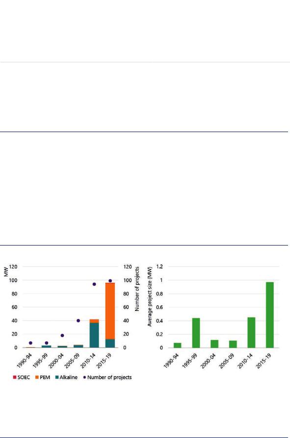
There has been an increase in new electrolysis installations over the last decade aimed at producing hydrogen from water, with PEM technology making significant inroads into the market. Geographically most of the projects are in Europe, although projects have also been started or announced in Australia, China and the Americas. The average unit size of these electrolyser additions has increased in recent years from 0.1 MWe in 2000–09 to 1.0 MWe in 2015–19, indicating a shift from small pilot and demonstration projects to commercial-scale applications. This should start to create economies of scale that will help to drive down capital costs and to scale up the supply chain of the electrolyser industry (Figure 10). Several projects under development have electrolyser sizes of 10 MWe or above, and some projects with electrolyser sizes of 100 MWe or larger are now under discussion.
Figure 10. Development of electrolyser capacity additions for energy purposes and their average unit size, 1990–2019
Note: Capacity additions refer to already installed capacity additions and are cumulated over the specified 5-year periods.
Sources: IEA analysis based on Chehade et al. (2019), “Review and analysis of demonstration projects on Power-to-X pathways in the world”, IEA (2018), World Energy Investment, and the World Energy Council (2018), “Hydrogen an enabler of the Grand Transition” and data provided by IEA Hydrogen Technology Collaboration Programme.
Global electrolyser capacity additions for energy purposes have been growing rapidly in recent years, and installations have been growing in size, providing cost reductions from economies of scale and learning effects.
PAGE | 45
IEA. All rights reserved.