Материал: Апсе ENVIRONMENTAL PROTECTION 2014
Similar expressions can be obtained for the depleting branch:
|
|
|
|
XW |
= |
1 |
|
|
× |
XF |
|
|
|
|
||||||||
|
|
|
|
|
(1) |
|
|
|
|
|
|
|
|
|
; |
|
|
|||||
|
1 - XW |
1 + e¢¢ |
1 - XF |
|
|
|||||||||||||||||
|
XW |
|
(NW ) = |
|
|
|
|
1 |
|
|
|
|
× |
|
XF |
. |
|
|||||
|
|
|
|
|
|
|
|
|
|
|
|
|
|
|
- XF |
|
||||||
|
1 - XW |
|
(1 + e¢¢)NW 1 |
|
|
|||||||||||||||||
So, |
|
|
|
|
|
|
|
|
|
|
|
|
|
|
|
|
|
|
|
|
|
|
|
ln |
XF / (1 − XF ) |
|
|
|
|
|
|
|
|
|
|
|
|
||||||||
NW = |
XW / (1 - XW ) |
» |
1 |
|
× ln |
XF / (1 - XF ) |
. |
|||||||||||||||
|
|
|||||||||||||||||||||
|
|
e¢¢ |
|
|||||||||||||||||||
|
|
|
ln(1 + e¢¢) |
|
|
|
|
|
|
|
|
XW / (1 - XW ) |
||||||||||
Let assume that it is necessary to produce weapon-grade uranium (XP = 90% 235 U) from natural uranium (XF = 0, 71% 235 U) by the GDtechnology (ε′ = ε′′ = 0, 0043) with 235U content in the waste XW = 0, 2% 235 U . Then, the numbers of the enriching stages and the depleting stages are equal NP ≈ 1660 and NW ≈ 290, respectively. If reactor-grade uranium (XP = 4% 235 U) must be produced from natural uranium with the same 235U content in the waste (0,2%), then the number of the enriching stages decreases to NP ≈ 410 at the same number of the depleting stages ( NW ≈ 290 ).
1.2.4. Uranium enrichment in gas centrifuges
If a cylindrical vessel (centrifuge) containing a binary mixture of light and heavy gases rotates with angular velocity w, then the centrifugal force acts on the elementary volume of the gaseous mixture:
F1,2 (r) = g1,2 ×w2 × r;
51
where γ1,2 − densities of the gaseous components; r – distance f rom cen-
ter of the vessel.
The pressures on the gaseous components can be determined with application of the following differential equation:
dP1,2 (r) |
= F (r) = g |
1,2 |
× w2 |
× r. |
(5) |
|
|||||
dr |
1,2 |
|
|
|
|
|
|
|
|
|
By using the Mendeleev-Clapeyron equation:
P (r) × V = |
m |
× R × T; |
|
||
1,2 |
M1,2 |
|
|
|
(M1, M2 – molecular masses of the gaseous components), den sities of the gaseous components can be determined:
g (r) = |
m |
= |
P1,2 |
(r) × M1,2 |
. |
|
|
|
|||
1,2 |
V |
|
|
R ×T |
|
|
|
|
|
Then, differential equation (5) can be re-written
|
|
dP1,2 (r) |
= |
P1,2 (r) × M1,2 |
×w2 × r; |
|
|
|
|||
|
|
dr |
|
|
|
|
|||||
|
|
|
R ×T |
|
|
|
|
|
|||
and solved: |
|
|
|
|
|
|
|
|
|||
|
|
M × w2 × r2 |
|
|
|
M × V2 |
|
|
|||
P1,2 |
(r) = P(0) × exp |
|
1,2 |
|
|
= P(0) × exp |
1,2 |
|
; |
||
|
2 × R × T |
2 × R × T |
|||||||||
|
|
|
|
|
|
|
|
||||
|
|
|
|
|
|
|
|
|
|
|
|
where V – linear velocity.
Evidently, content of the light and heavy components in the gaseous mixture are proportional to the spatial pressure distribution:
52

|
|
|
|
|
|
|
|
|
|
MLIGHT × V2 (r) |
||
X |
235 |
(r) = X |
235 |
(0) × exp |
|
|
; |
|||||
|
|
|||||||||||
|
|
|
|
|
|
2 × R × T |
|
|||||
|
|
|
|
|
|
|
|
|
|
|
||
|
|
|
|
|
|
|
|
|
MHEAVY × V2 (r) |
|||
X |
238 |
(r) = X |
238 |
(0) × exp |
|
|
|
. |
||||
|
|
|
||||||||||
|
|
|
|
|
|
2 × R × T |
|
|
||||
|
|
|
|
|
|
|
|
|
|
|
|
|
These formulas demonstrate that content of the heavy component (depleted uranium) is larger in peripheral region of the centrifuge, and, vice versa, content of the light component (enriched uranium) is larger in central region of the centrifuge. In this case, the single-stage enrichment factor can be determined from the following expressions:
a= X235 (0) / X238 (0) = exp (-MLIGHT × V2 (r) 2 × R × T) =
(r)X235 (r) / X238 (r) exp (-MHEAVY × V2 (r) 2 × R × T)
= exp (DM × V2 (r) 2 × R × T);
e¢(r) = a(r) -1 » DM × V2 (r) ). 2 × R × T
As is seen, the single-stage enrichment gain ε′ of the GC-technology depends only on absolute, not relative like in the GD-technology, difference of molecular masses of the light and heavy gas components. Also, the single-stage enrichment gain is proportional to the squared linear velocity of the centrifuge rotation. The centrifuges of contemporary designs can rotate with linear velocities up to 500-700 m/s, i.e. near to the velocity of a bullet outgoing from the rifle tube. According to many numerical evaluations, the GC-technology can provide the following velocity-dependent values of the single-stage enrichment gain at the outer centrifuge radius r0:
e′(r0 ) = 0, 068 at V = 330 m / s; e′(r0 ) = 0, 098 at V = 400 m / s; e′(r0 ) = 0,152 at V = 500 m / s;
e′(r0 ) = 0,300 at V = 700 m / s.
53
The gas centrifuges are currently being made of the following structural materials:
1.Aluminum-based alloys for linear velocities V ≤ 350 m/s.
2.Titanium-based alloys for linear velocities V ≤ 450 m/s.
3.Alloyed steels for linear velocities V ≤ 500 m/s.
4.Graphite-reinforced glass-fiber plastics for linear velocities V = 500-
700m/s.
If vertical gas circulation can be arranged in the centrifuge (for example, by thermal convection caused by temperature gradient between top and bottom parts of the centrifuge), then the centrifuge can act as the enriching cascade. The gaseous mixture goes upwards along central
axis and then goes downwards along the centrifuge wall. So, the gaseous mixture of 235UF6 and 238UF6 is being continuously enriched with the heavy component in the peripheral bottom region while the gaseous mixture is gradually enriched with the light component in the central top region of the centrifuge.
The gas flow going upwards in the center and downwards at the periphery can be formed by an insignificant warming-up of the central region. The warming-up effect can be produced by a small electrically heated rod placed in the centrifuge center.
1.2.5. Separation nozzle technology
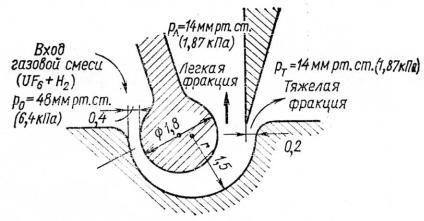
The separation-nozzle (SN) technology has been developed at the Karlsruhe Nuclear Research Center (Germany) as an alternative to the GDand GC-technologies. The gaseous mixture UF6 and hydrogen (or helium) expands along a bent wall. The centrifugal deflection force can split the flow into the light and heavy fractions by means of a slimmer (Fig. 1.4).
54
|
|
|
|
|
|
|
|
PL=14 mm Hg |
|
|
|
|
||||
|
|
|
|
|
|
|
|
|
|
|
|
|
|
|
|
|
|
|
|
|
|
|
|
|
|
|
|
|
|
|
|
|
|
|
|
Gaseous |
|
|
|
|
|
|
|
|
|
|
|
|
||
|
|
|
|
|
|
|
|
|
|
|
|
|
|
|||
|
|
mixture |
|
|
|
|
|
|
Light |
|
|
PH = 14 mm Hg |
||||
|
|
|
|
|
|
|||||||||||
|
|
(UF6+H2) |
|
|
|
|
|
fraction |
|
|||||||
|
|
|
|
|
|
|
|
|
|
Heavy |
|
|||||
|
|
|
|
|
|
|
|
|
|
|
||||||
P0 = 48 mm Hg |
|
|
|
|
|
|
||||||||||
|
|
|
|
|
|
|
|
fraction |
|
|||||||
|
|
|
|
|
|
|
|
|
|
|
|
|
|
|
|
|
|
|
|
|
|
|
|
|
|
|
|
|
|
|
|
|
|
Nozzle
Fig. 1.4. Layout of the separation-nozzle technology
The hydrogen or helium auxiliary gas (gas-carriers) increases the flow velocity and, hence, it increases the centrifugal forces defining efficiency of the SN-process.
The SN-technology is profitably distinguished from the GCtechnology by the absence of the rotating details but it requires a very fine mechanical assemblage because of very little sizes of the splitting slits (decimal fractions of one millimeter). The single-stage enrichment gain in the SN-technology can reach ε′ ≈ 0, 025 at the specific energy consumption about 3000 kWh/SWU.
1.2.6. Laser technologies of isotope separation
The laser technologies of uranium enrichment rely on the slightly different excitation energies of electronic shells that surround 235U and 238U nuclei. Three extra neutrons in 238U nucleus caused the slight shift in the electron excitation energy scheme as compared with 235U nucleus. This energy shift can be used to excite selectively uranium atoms or uranium-containing molecules by the monochromatic laser light properly tuned to the required wavelength. The excited state of electronic shell can selectively enhance some physical or chemical processes with uranium-containing materials and, thus, promote isotope separation.
55