Материал: Апсе ENVIRONMENTAL PROTECTION 2014
1. Reaction of U3O8 with gaseous fluorine at 350-3700С that leads to the formation of uranyl-fluoride UO2F2:
U3O8 + 3F2 → 3UO2F2 + O2.
2. Reaction of uranyl-fluoride with gaseous fluorine at slightly reduced temperature ( 2700С):
UO2F2 + 2F2 → UF6 + O2.
Another one-step process is feasible too. The one-step process is based on the direct high-temperature fluorination technology. However, the process is feasible only at excess amounts of gaseous fluorine and at substantially higher temperatures (900-10000С):
U3O8 + 9F2 → 3UF6 + 4O2.
In the closed NFC with recycling of the regenerated uranium, uranium dioxide UO2 extracted from spent fuel assemblies is an initial material for its conversion into uranium hexafluoride. In this case the following two-step fluorination process is usually applied:
1. Reaction of uranium dioxide with hydrofluoric acid at 500-6000С that leads to the formation of uranium tetra-fluoride UF4:
UO2 + 4HF → UF4 + 2H2O.
2. Reaction of uranium tetra-fluoride with gaseous fluorine at 4000С:
UF4 +F2 = UF6
Afterwards, uranium hexafluoride is condensed at -150С and can be transported in the containers made of nickel-based alloys.
1.2.3. Uranium enrichment by gas diffusion technology
Gas diffusion (GD) is a physical phenomenon of mass transport in a mixture of different gases caused by their thermal movements.
46
The GD-technology of material separation is based on different thermal velocity of light and heavy molecules, and on different penetrability of light and heavy molecules through porous walls (membranes).
In binary mixture of light and heavy gases both components have the same temperature and, thus, the same kinetic energy:
mLIGHT × VLIGHT2 = mHEAVY × VHEAVY2 .
So, the light molecules can move with higher velocity and, as a consequence, can penetrate through a porous wall with larger probability:
VLIGHT = (mHEAVY / mLIGHT )1/ 2 .
VHEAVY
In principle, it can be shown that the maximal, theoretically achievable ideal separation factor a0 for two gases diffusing through a porous wall is equal to:
a0 |
= |
VLIGHT |
= (mHEAVY mLIGHT )1 2 »1 + |
Dm |
. |
|
|
||||
|
|
VHEAVY |
2mLIGHT |
||
Molecular masses of 235UF6 (the light gas) and 238UF6 (the heavy gas) are equal to 349 a.m.u. and 352 a.m.u., respectively. Thus:
′ |
= a0 -1 = 0, 0043. |
a0 =1, 0043; e0 |
Efficiency of the GD-technology can be upgraded if the mean free path l of UF6 molecules is much longer than typical size of pores a (l>>a) because main mechanism of thermal movements must be mole- cule-pore interactions, not inter-molecular collisions. The mean free path of any gaseous molecules is inversely proportional to the pressure. For example, the mean free path of UF6 molecules is equal to ~1 micron at atmospheric pressure and to ~700 microns at 1 mm Hg.
47
Manufacturing of the GD-membranes with the micron-level sizes of pores is a very complicated and the most classified problem. The porous walls must be:
1.thin (well below 1 mm);
2.strong (under the pressure drop up to 0,3 atmosphere);
3.corrosion-resistant in the UF6 environment.
Currently, the porous tubular elements for the GD-technology are
being made of the following materials:
1.sintered powders of alumina and nickel oxide;
2.sintered nickel powder;
3.porous aluminum produced by the electrical etching technology. Typical parameters of the GD-technology: the temperature range –
65÷110 0C, the pressure - 0,35 atmosphere, the pressure drop - 0,3 atmosphere.
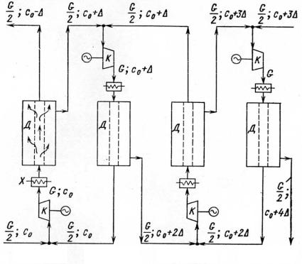
Cascading of the GD-process. Since the single-stage enrichment gain that can be achieved by the GD-technology is very small (0,0043), many successive GD-stages have to be used to reach necessary values of uranium enrichment (for example, up to 5% 235U for nuclear power reactors or above 90% 235U for nuclear weaponry). System of the successively linked GD-stages constitutes the GD-cascade with two different separation branches (Fig. 1.2): the depleting branch where relative 235U content reduces from 0,71% in natural uranium (the feed material) down to 0,2-0,3% in the depleted uranium (the waste material or tails), and the enriching branch where relative 235U content increases from 0,71% in natural uranium up to the necessary values (5%÷90% 235U).
Experimental studies have shown that the best arrangement for the successive GD-stages is that in which half the gas flow pumped into each stage diffuses through the porous wall to the next higher (enriching) stage, the other half being returned to the feed material of the lower stage.
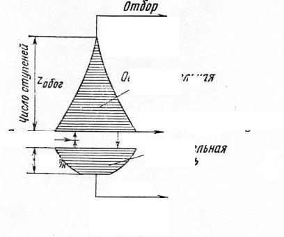
Evidently, the numbers of the GD-stages and UF6 flow rates are different in the enriching and the depleting branches. These values depend on 235U content in the product and in the waste. It is clear that relatively small number of the depleting stages is required to reduce 235U content from 0,71% in natural uranium down to 0,2-0,3% in the waste. On the contrary, relatively large number of the enriching stages is required to upgrade 235U content from 0,71% in natural uranium up to 5% 235U (re-
48
actor-grade uranium) or 90% 235U (weapon-grade uranium) in the product. The flow rates of uranium hexafluoride successively reduce in both branches but the reduction of UF6 flow rate is sharper in the enriching branch. The sharper reduction can be explained by the following consideration. In the extreme case of producing 100% 235U in the product and 0% 235U in the waste from 1000 kg of natural uranium, final stages of the enriching branch would handle with 8-10 kg of the enriched uranium while final stages of the depleting branch would handle with 990 kg of the depleted uranium (Fig. 1.3).
|
|
|
C |
|
|
|
|
C |
||
|
|
|
|
|
|
|
|
|
|
|
|
|
|
|
|
|
|
|
|
|
|
|
|
|
|
|
|
|
|
|
|
|
|
|
|
|
|
|
|
|
|
|
|
|
|
|
|
|
|
|
|
|
|
|
|
|
|
|
|
|
|
|
|
|
|
HX |
|
|
|
|
|
|
|
|
|
HX |
|
|
|
|
|
|
|
|
||
|
|
|
|
|
|
|
|
|
|
|
|
|
|
|
|
C |
|
|
|
C |
Step n-1 Step n Step n+1 Step n+2
Fig. 1.2. Layout of the GD-cascade
The numbers of the enriching and the depleting stages in the GDcascade can be evaluated following form the definitions of the singlestage enrichment ε′ and depletion ε′′ gains.
49
The following expressions can be written for uranium enrichment after the first enriching stage and, then, after NP enriching stages:
|
|
XP |
(1) = (1 |
+ e¢) × |
XF |
|||||||||||
|
|
|
|
|
|
|
|
; |
|
|
||||||
|
|
1 - XP |
1 - XF |
|||||||||||||
|
XP |
(NP ) = (1 + e¢)NP × |
|
XF |
. |
|
||||||||||
|
|
|
|
|
||||||||||||
|
1 - XP |
|
|
|
|
|
1 |
- XF |
||||||||
So, |
|
XP / (1 - XP ) |
|
|
|
|
|
|
|
|
|
|
||||
|
ln |
|
|
|
|
|
|
|
|
|
|
|||||
NP = |
|
|
- XF ) |
» |
1 |
× ln |
XP / (1 - XP ) |
. |
||||||||
|
XF / (1 |
|||||||||||||||
|
|
|
|
|
e¢ |
|
||||||||||
|
|
ln(1 + e¢) |
|
|
|
XF / (1 - XF ) |
||||||||||
|
|
|
|
|
|
|
|
|
|
|
|
|
|
|
|
|
|
|
|
|
|
|
|
. |
|
Np |
|
|
|
|
|
|
|
|
|
|
|
|
|
|
|
|
|
|
|
|
Feed F, XF
Nw 
Enriched uranium P, XP
 Enriching

branch
UF6 flow rate
Depleting
branch 
Depleted uranium W, XW
Fig. 1.3. Reduction of the stage quantity and uranium flow rate in the GD-branches
50